Cartridge holder

a cartridge and holder technology, applied in the field of cartridge holders, can solve the problems of affecting the use of the cartridge, the inside edge of the cartridge, and the possibility of damaging the shutter, etc., and achieve the effects of reducing the thickness of a given part, convenient handling, and easy construction

Inactive Publication Date: 2001-03-13
SONY CORP
View PDF8 Cites 41 Cited by
  • Summary
  • Abstract
  • Description
  • Claims
  • Application Information

AI Technical Summary

Benefits of technology

Accordingly, if the back portion is roundly flexed at the major hinge portions causing a plurality of cartridges gripped by the cartridge gripping parts to be opened like a fan, upper ends of the cartridges are separated and thus the upper ends can be easily handled by fingers of a user.
According to the invention, there is provided a cartridge...

Problems solved by technology

First, the manual work for removing the cartridges 201A and 201C from the cartridge receiving areas of the lid portions 106 and 107 is difficult or at least troublesome. That is, although the first and second engaging lugs 108a and 108b (or, 112a and 112b) and the third and fourth engaging stubs 108c and 108d (or, 112c and 112d) can tightly and assuredly hold the cartridge 201A or 201C, they fail to provide an easiness with which the cartridges 201A and 201C can be removed therefrom. That is, as is seen from FIG. 55, when a user wishes to remove the cartridge 201A from the cartridge receiving area of the lid portion 106, he or she has to pull up the inside side edge of the cartridge 201A with his or her finger "F" from the lid portion 201A against a gripping force applied thereto from the third and fourth engaging stubs 108c and 108d. However, in this case, it tends to occur that the finger "F" is injured particularly when the cartridge 201A has been tightly and assuredly held by the lid portion 106, that is, by the first, second, third and fourth engaging lugs and stubs 108a, 108b, 108c and 108d. Furthermore, due to the same reason, it tends to occur that the inside side edge of the cartridge 201...

Method used


Image

  • Cartridge holder
  • Cartridge holder
  • Cartridge holder

Examples


first embodiment

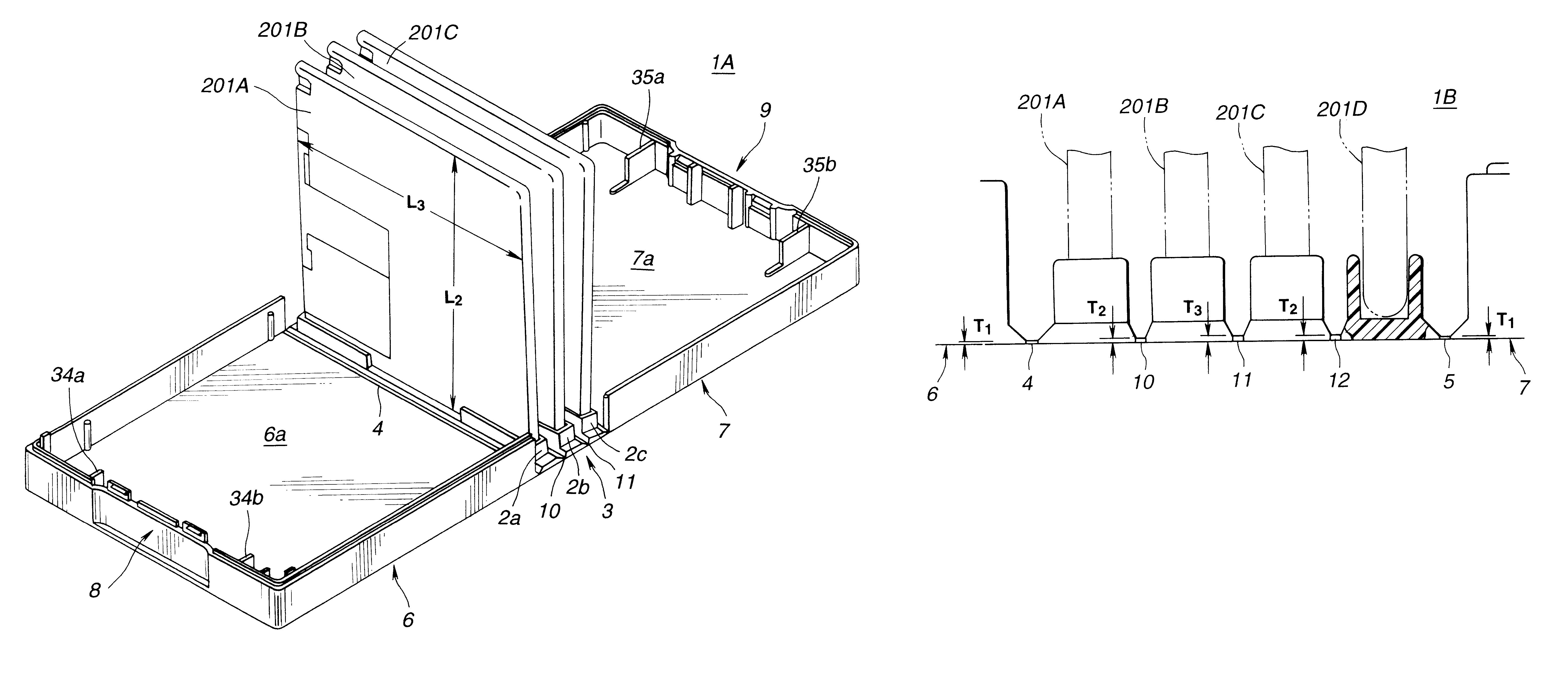
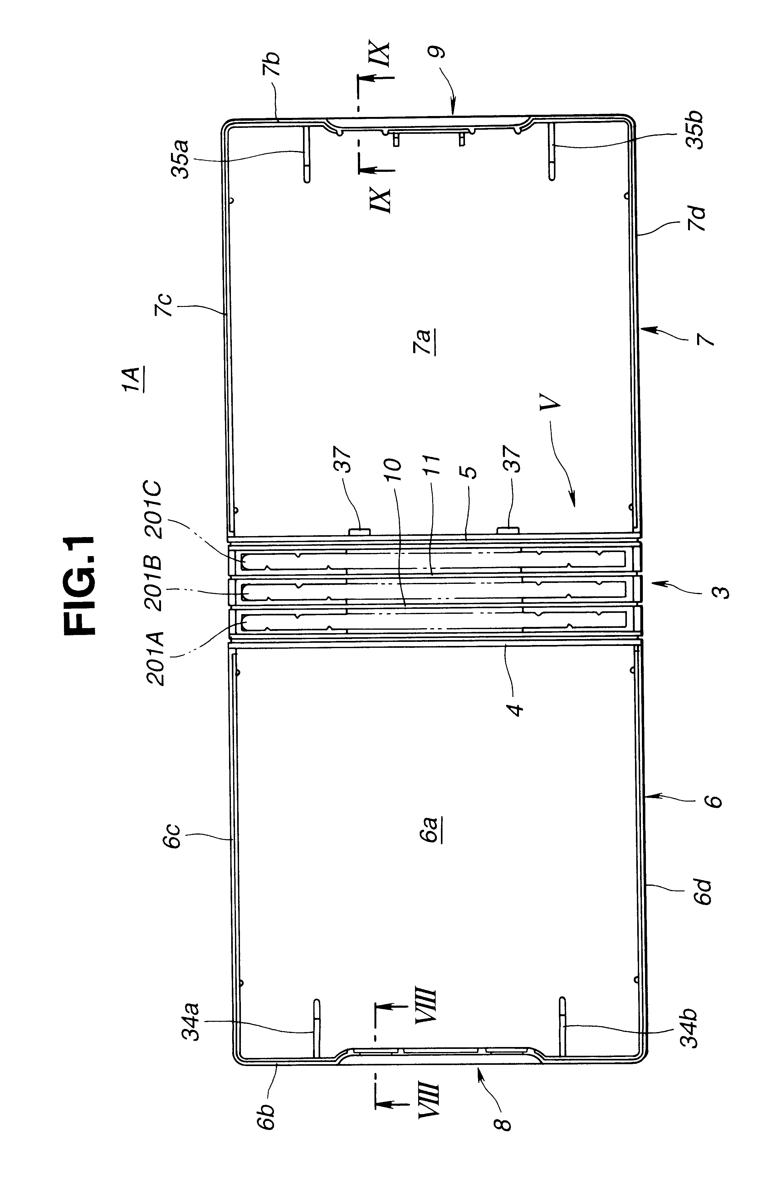
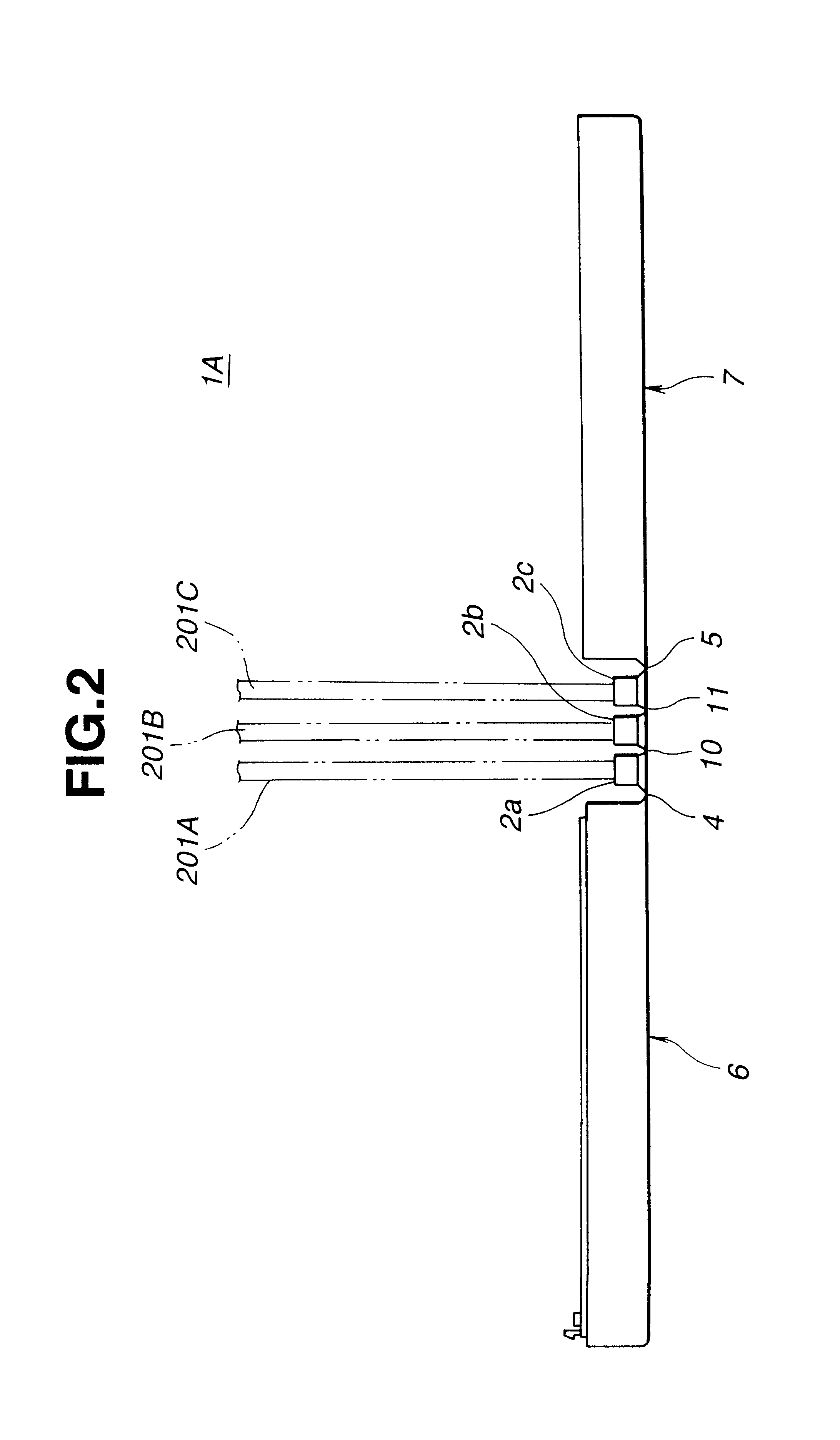
Referring to FIGS. 1 to 15, particularly FIGS. 1 and 7, there is shown a cartridge holder 1A of the present invention, which is made of a molded plastic and constructed to hold three floppy disc cartridges 201A, 201B and 201C.

As is best seen from FIG. 7, the cartridge holder 1A of this embodiment comprises generally a pair of lid portions 6 and 7, a back portion 3 having on its inner surface first, second and third cartridge gripping parts 2a, 2b and 2c, first and second outside hinge portions 4 and 5 through which the lid portions 6 and 7 are pivotally connected to the back portion 3, a catching portion 8 formed on a free end of the lid portion 6 and a caught portion 9 formed on a free end of the other lid portion 7.

The back portion 3 has further a third inside hinge portion 10 through which the first and second cartridge gripping parts 2a and 2b are pivotally connected and a fourth inside hinge portion 11 through which the second and third cartridge gripping parts 2b and 2c are pi...

second embodiment

Referring to FIGS. 16 to 18, there is shown a cartridge holder 1B of the present invention.

As is seen from FIG. 16, the cartridge holder 1B of this second embodiment is substantially the same as that 1A of the first embodiment except that in the second embodiment 1B, four, that is, first, second, third and fourth cartridge gripping parts 2a, 2b, 2c and 2d are defined. Due to addition of the fourth cartridge gripping part 2d, a fifth hinge portion 12 is defined on the back portion 3 between the third and fourth cartridge gripping parts 2c and 2d.

As is seen in FIG. 18, in the second embodiment 1B, the thickness "T1" of the first and second hinge portions 4 and 5 is smaller than the thickness "T2" of the third and fifth hinge portions 10 and 12, and the thickness "T2" is smaller than the thickness "T3" of the fourth hinge portion 11. That is, an inequality "Ti

Substantially the same advantage as the above-mentioned first embodiment 1A is obtained in this second em...

third embodiment

Referring to FIGS. 19 to 23, there is shown a cartridge holder 1C of the present invention.

Since the cartridge holder 1C of this third embodiment is similar in construction to that 1A of the above-mentioned first embodiment, only parts and construction which are different from those of the first embodiment 1A will be described in the following.

That is, in this third embodiment, the cartridge retaining ribs 34a, 34b, 35a and 35b formed on the lid portions 6 and 7 are improved in construction.

As is seen from FIG. 21, in a closed condition of the cartridge holder 1C, the distance "L1" between the bottom surface of each cartridge gripping part 2a, 2b or 2c and the stopper edge 34a', 34b', 35a' or 35b' of the retaining rib 34a, 34b, 35a or 35b is somewhat greater than the width "L2" of the cartridge 201A, 201B or 201C, but smaller than the length "L3" (see FIG. 13) of the same. Furthermore, the height "H1" of the cartridge gripping part 2a, 2b or 2c (that is, the distance between the dep...


PUM


Abstract

A cartridge holder is shown which comprises a back portion which has at an inner surface a plurality of cartridge gripping parts by which one sides of cartridges are gripped, a pair of lid portions which are pivotally connected to opposed sides of the back portion through respective major hinge portions; catching and caught portions which are provided at free ends of the lid portions and lock the lid portions when the lid portions are pivoted toward their closed position; and a plurality of extra hinge portions which are defined by the back portion. By roundly flexing the back portion at the major hinge portions, the cartridge gripping parts, that is, the cartridges gripped by these cartridge gripping parts are opened like a fan. Thus, upper ends of the cartridges are separated thereby facilitating handling of the upper ends of the cartridges by the fingers of a user. In order to prevent a swell-out phenomenon of the back portion which would occur when the back portion is roundly flexed, there is provided a swell-out phenomenon suppressing means. In order to prevent removal of the cartridges from the cartridge gripping parts which would occur when vibration and shock are applied thereto under conveying of the holder, there is provided a cartridge retaining rib.

Description

The present invention relates in general to holders for holding a plurality of cartridges, such as floppy disc cartridges or the like, and more particularly to the holders of a type which is constructed to steadily hold therein the cartridges and facilitate the work for removing the cartridges from the holder.In order to clarify the task of the present invention, one conventional cartridge holder will described with reference to FIGS. 52 to 57 of the accompanying drawings, which is generally designated by numeral 101. The cartridge holder 101 is constructed to hold three identical floppy disc cartridges 201A, 201B and 201C.As is best shown in FIG. 52, the cartridge holder 101 comprises generally a pair of lid portions 106 and 107, a hinge portion 103 through which the lid portions 106 and 107 are pivotally connected, a catching portion 109 formed on a free end of the lid portion 106 and a caught portion 110 formed on a free end of the other lid portion 107. Each of the lid portions ...

Claims


Application Information

Patent Timeline
IPC IPC(8): G11B33/04
CPCG11B33/0438B65D85/544
Inventor HIGUCHI, SHINTAROABE, YOSHIYUKIMEGURO, HIROSHI
Owner SONY CORP
Why Eureka
Try Eureka