Take-up frame system and method with force feedback

a technology of force feedback and take-up frame, which is applied in the direction of shaft and bearing, gearing, rotary bearing, etc., can solve the problems of accelerating component wear and eventual failure, conventional take-up frame structure, and failure to take into

Inactive Publication Date: 2001-03-13
BALDOR ELECTRIC COMPANY
View PDF5 Cites 38 Cited by
  • Summary
  • Abstract
  • Description
  • Claims
  • Application Information

AI Technical Summary

Problems solved by technology

Several drawbacks exist in conventional take-up frame structures.
While certain operators may accurately judge loads during steady state operation, even these operators may fail to take into account excessive loading which can result during intermittent phases of operation.
Where an inexperienced operator places too little load on the system, slack can occur, leading to accelerated component wear and eventual failure.
Where excessive loading is placed on the structure, excessive heating can occur in the bearing, leading to its premature failure.
Moreover, in systems employing take-up frames on either side of a rotating member, such as in conveyer systems, inconsistent loading on either side of the rotating component can lead to misalignment and tracking problems, as well as to uneven and excessive loading and failure of both the conveyer belt and the bearings.
In summary, non-uniform or excessive loading of take-up frame supported systems may result in excessive bearing heating, pulley shaft deflection, bushing fatigue, and belt carcass damage, all potentially leading to costly downtime and maintenance.

Method used


Image

  • Take-up frame system and method with force feedback
  • Take-up frame system and method with force feedback
  • Take-up frame system and method with force feedback

Examples


Embodiment Construction

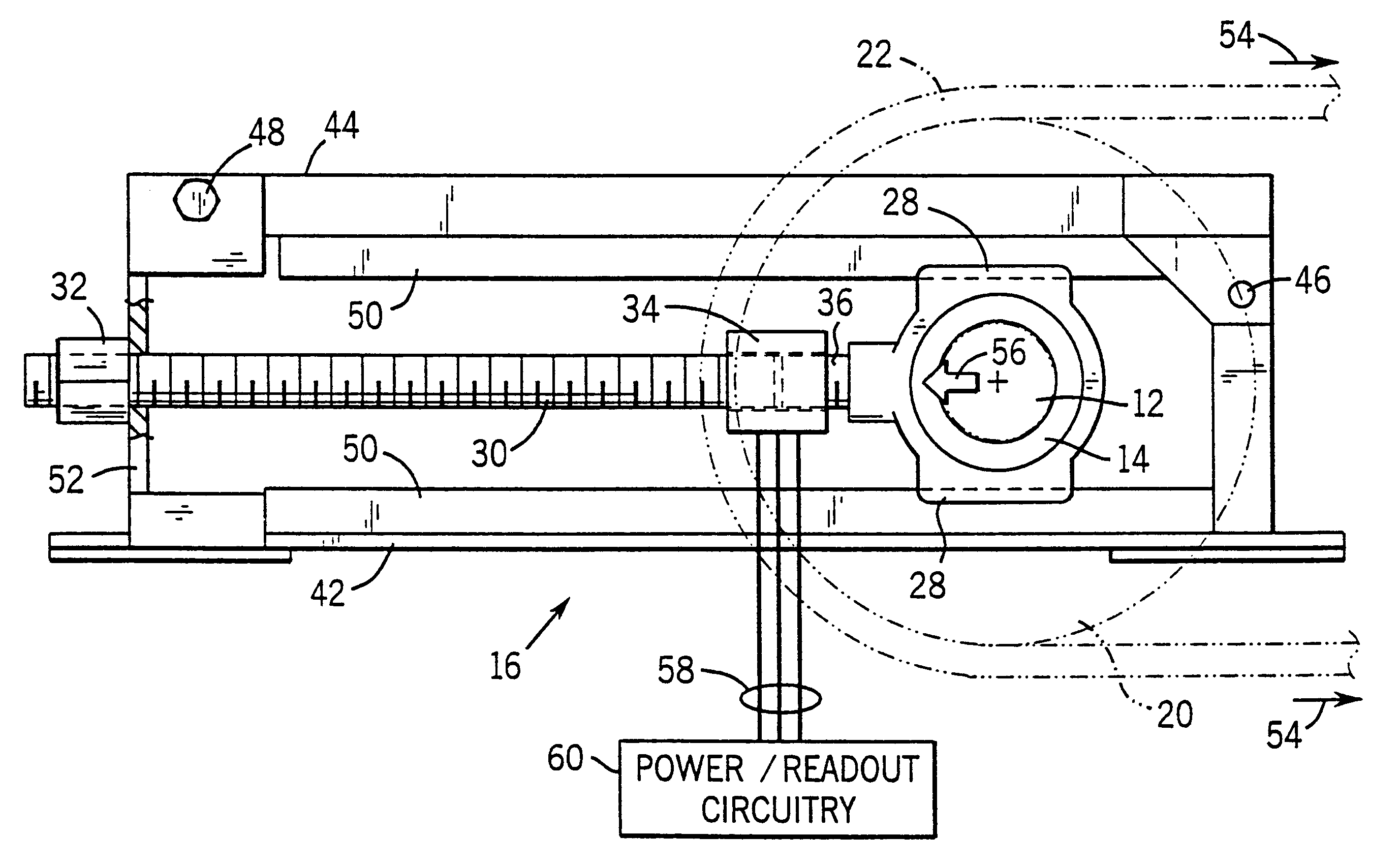
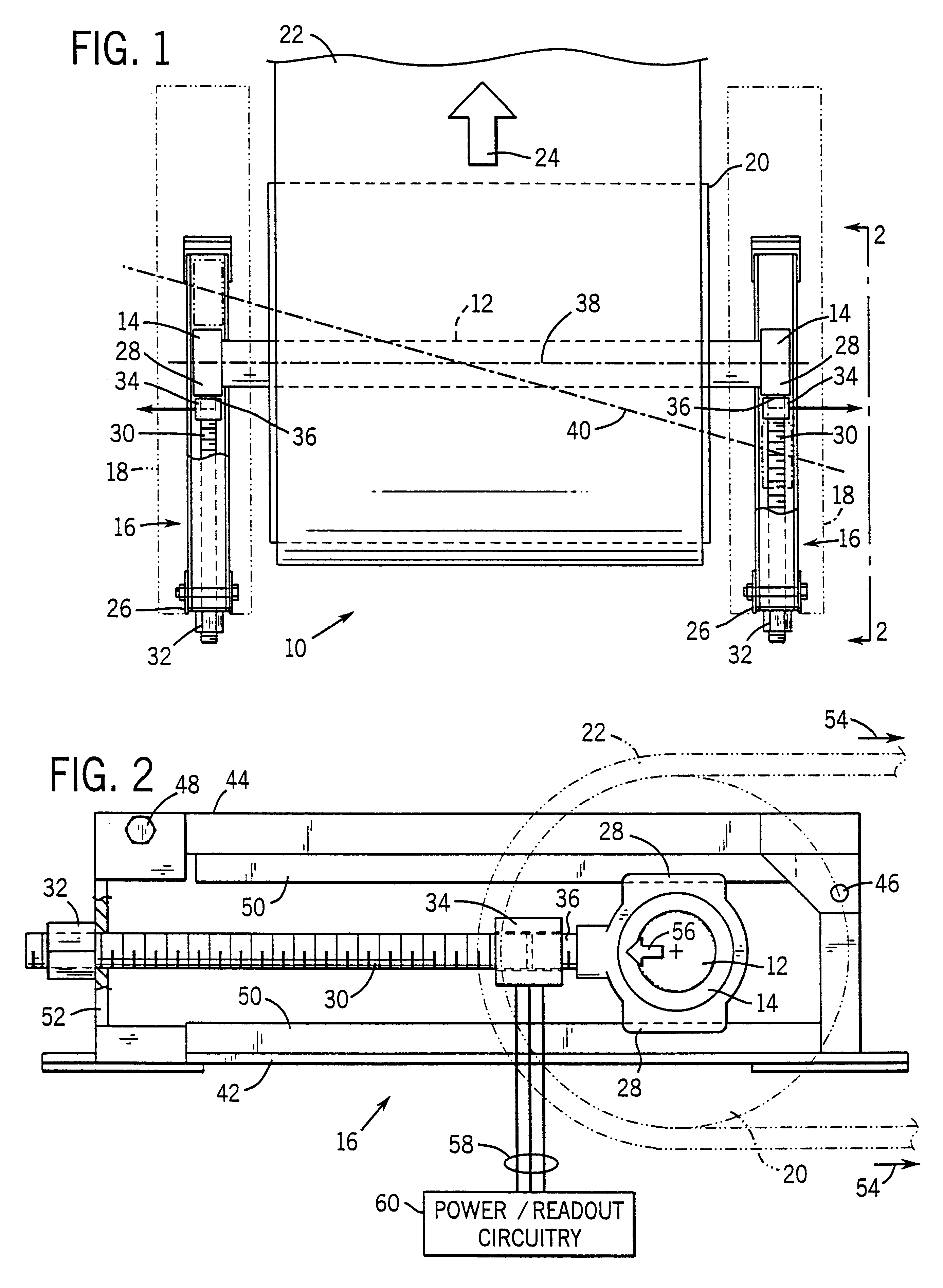
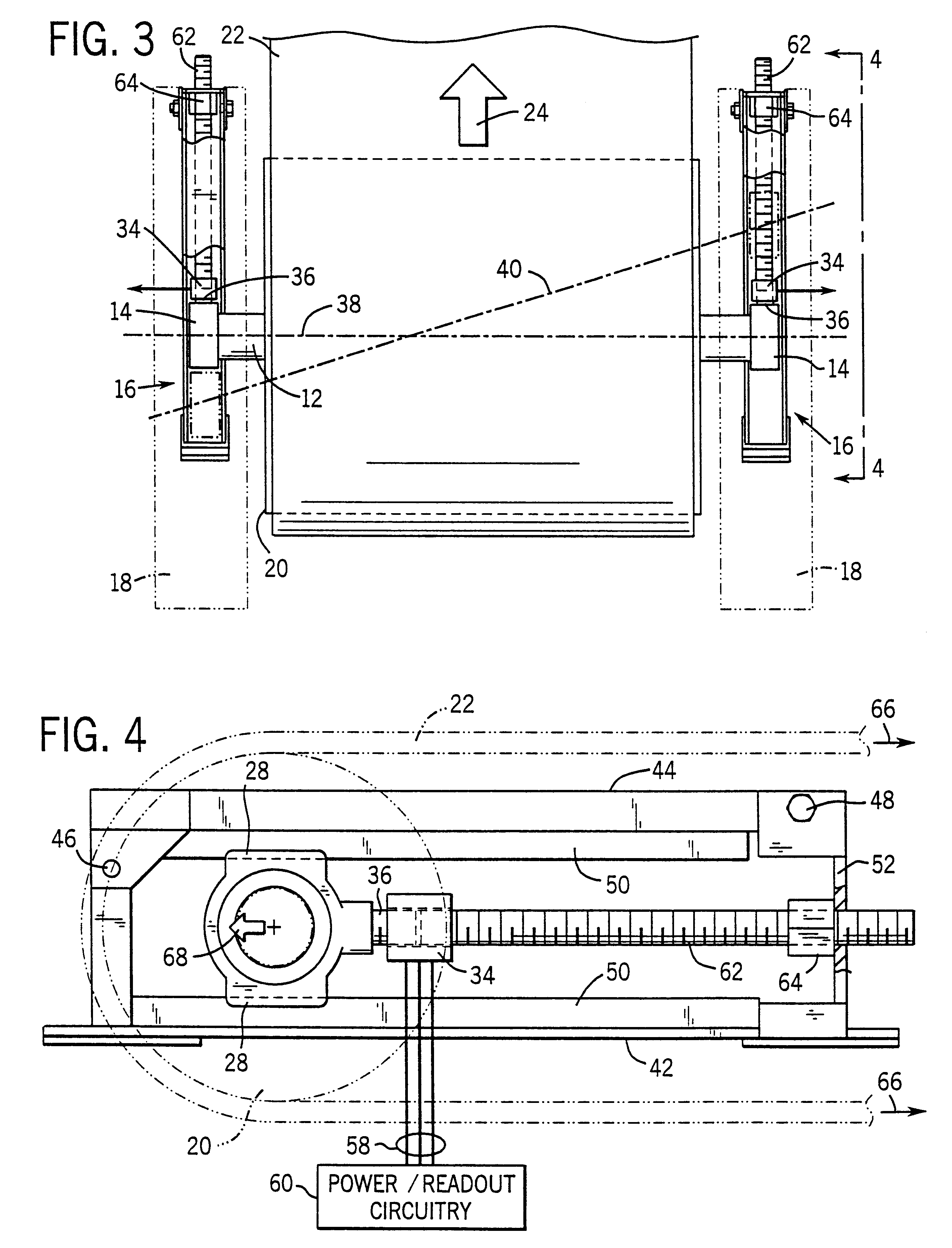
Turning now to the drawings, and referring first to FIG. 1, a take-up frame system, designated generally by reference numeral 10, is illustrated as applied to lateral sides of a belt conveyor. System 10 includes a shaft 12 supported on both ends by bearing sets 14. While both active (i.e. driven) and passive (i.e. idler) shafts may be employed with the take-up frame adjustment technique described herein, in a conveyor application, take-up frames will typically be applied to a passive shaft or pulley assembly at an end of a conveyor belt distal from a motor and drive arrangement. To maintain appropriate loading on bearings and on the conveyor belt, take-up frames 16 are provided, in which bearings 14 may be slidingly adjusted to position shaft 12 as desired.

Take-up frames 16 are mounted on any appropriate machine support 18, such as a stand or support framework. In the illustrated embodiment, a pulley 20 is fixed to shaft 12 and rotates therewith. A belt 22 is passed about pulley 20 ...


PUM


Abstract

A take-up frame assembly is instrumented with a sensor for detecting tensile or compressive loading on the assembly during adjustment. A visual readout of the loading is provided as feedback to an operator in making system adjustments. The readout may be resident at the take-up frame, or part of a portable module coupled to the sensor during adjustment. In systems including a pair of take-up frames on either side of a machine, such as a pulley-driven belt conveyor, the sensor and feedback arrangement can be used to balance forces on both sides of the system to achieve the desired operational belt tension.

Description

1. Field of the InventionThe present invention relates generally to the field of take-up frames and similar structures for maintaining desired force or alignment of rotating machinery. In particular, the invention relates to a system for providing feedback of forces exerted on a bearing set in a take-up frame, permitting a system or operator to regulate the force at the desired level.2. Description of the Related ArtIn rotating equipment, bearing assemblies are traditionally provided for securing a rotating element, typically a shaft, with respect to support or stationary components. By way of example, in conveyer belts, chain drives, and similar systems, active or passive shafts are supported on anti-friction bearing assemblies for free rotation with a conveyor belt, chain assembly, or other transmission component. To maintain proper tension in these components, one end of the component is typically fixed in space such as on a driven pulley, while the opposite end is movable. The f...

Claims


Application Information

Patent Timeline
Patent Type & Authority Patents(United States)
IPC IPC(8): B65G23/44B65G23/00F16H7/08
CPCB65G23/44F16H2007/0891
Inventor GIRARDEY, GREG F.
Owner BALDOR ELECTRIC COMPANY
Why Eureka
Try Eureka