
Sliding body expanding broadhead

a broadhead and expanding technology, applied in the direction of arrows, weapons, ammunition projectiles, etc., can solve the problems of complex mechanical mounting of the rotatable blade, and achieve the effect of simple replacement, easy replacement and repair

Inactive Publication Date: 2001-03-13
OUT RAGE
View PDF5 Cites 92 Cited by
  • Summary
  • Abstract
  • Description
  • Claims
  • Application Information

AI Technical Summary

Benefits of technology

All of the elements of the Applicant's tip provide simply replaceable portions such that in the field replacement and repair may be easily accomplished. The Applicant's concept also provides for alignment of the cutting surfaces of the penetrating tip and the blades thereof.
Applicant's desi

Problems solved by technology

Many of these tips, however include a complex mechanical mounting for the rotatable blades of the tip.

Method used


Image

  • Sliding body expanding broadhead
  • Sliding body expanding broadhead
  • Sliding body expanding broadhead

Examples


Embodiment Construction

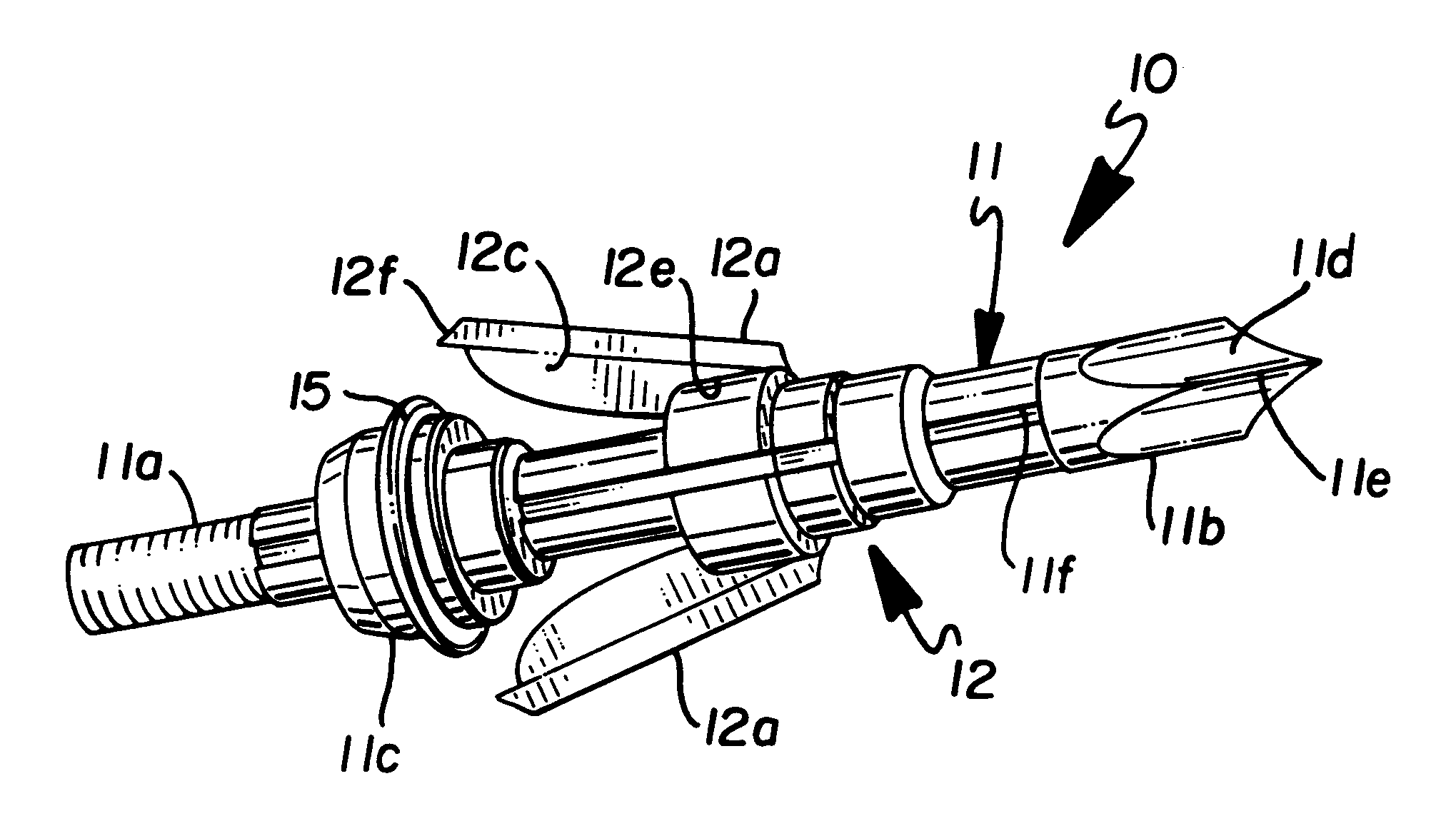
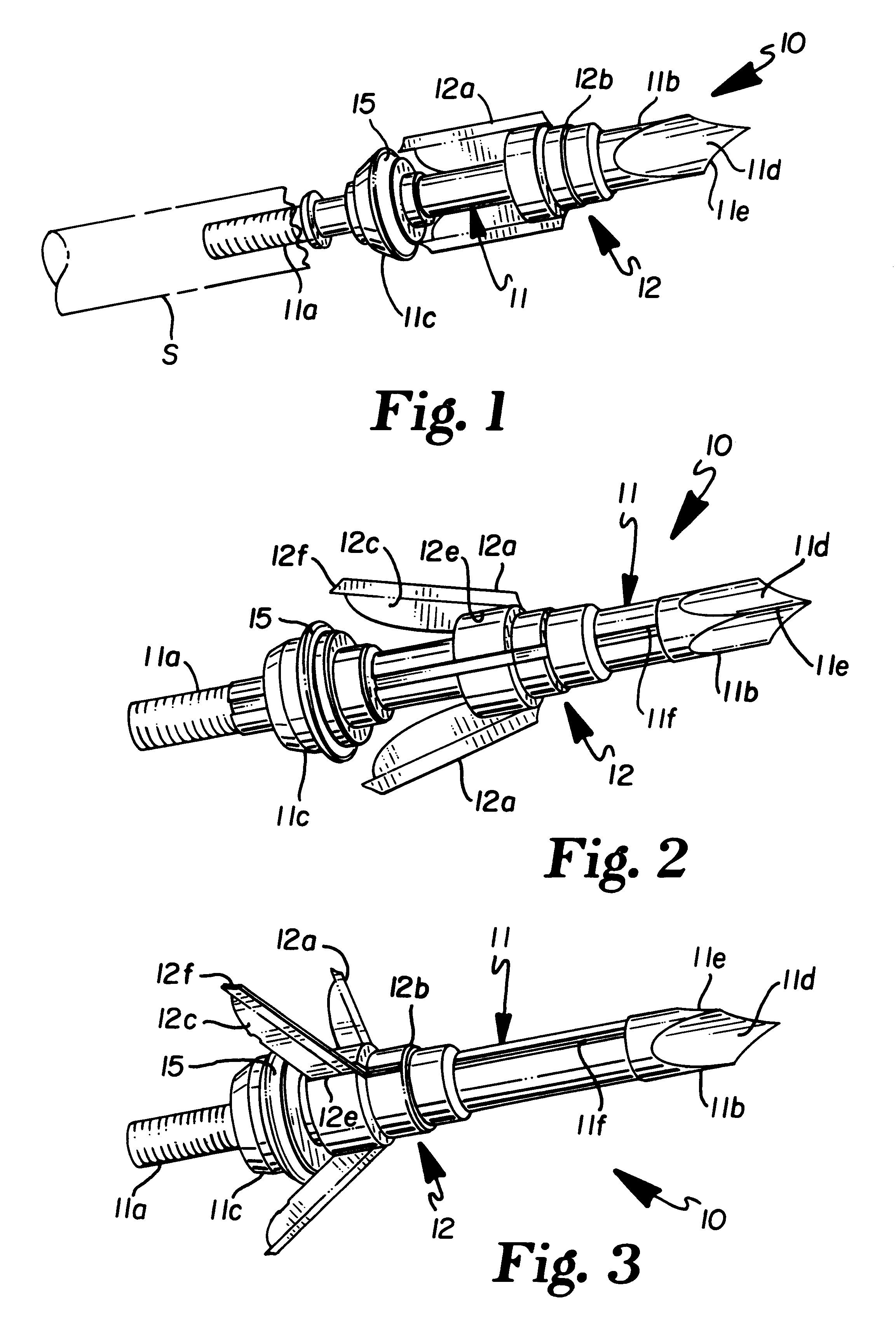
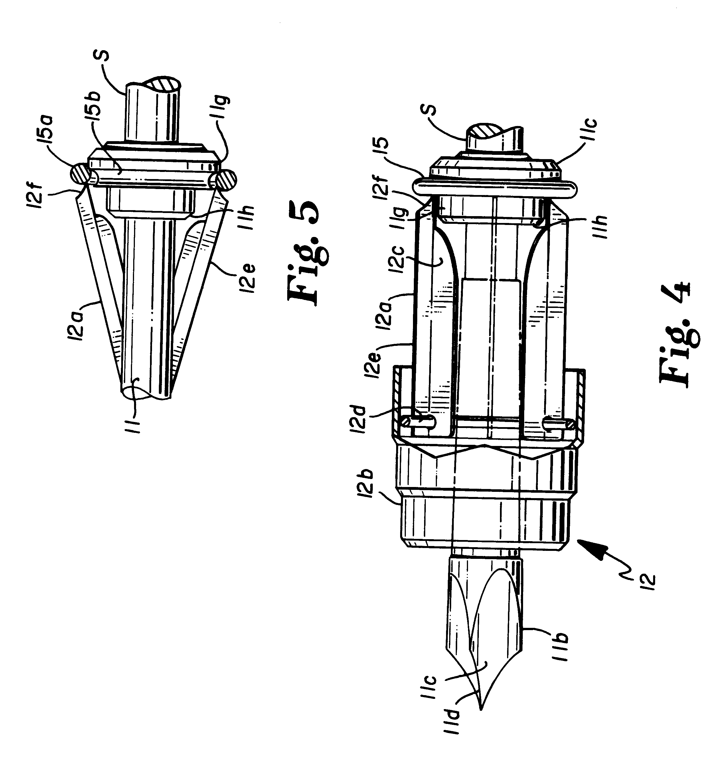
In accordance with the accompanying drawings, Applicant's expandable broadhead arrow tip is generally designated 10 and is illustrated mounted on the forwardmost end of an arrow shaft S.

The tip 10 includes a longitudinally extending body portion 11 having a threaded end 11a for mounting to shaft S, a penetrating end 11b and a stop 11c may be slidable along said body 11 to normally rest against the frontal surface of shaft S or may be positively located along said body 11, a predetermined distance from penetrating end 11b. Body 11 may be of reduced diameter with respect to either the tip 11b or stop 11c. As illustrated, the penetrating tip 11b is machined to provide at least a pair of and preferably a plurality of surfaces 11d with the meeting of adjacent pairs thereof providing a common edge 11e. Body 11 is provided with a set of grooves 11f, the number thereof being in agreement with the number of such tip edges 11e such that alignment will be afforded between such grooves, 11f, ti...


PUM


Abstract

An expanding or expandable broadhead tip for arrows wherein a sliding body is provided to carry the blades of the arrow and allow for rotation of the blades to an expanded position. When in folded or inflight position, the rearmost ends of the blades rest on a radial surface of a stationary or positionable stop having a camming front surface and which are held in such position by a retainer. When the tip strikes an object, the sliding body moves rearwardly causing the ends of the blades to override the hold down force of the retainer and as rearward motion continues, the blades are cammed outwardly by the camming front of the stop.

Description

Applicant has no and is aware of no applications for patent by others that should be considered with regard to the prosecution of this application.SPONSORSHIPApplicant has not been either Federally or Independently sponsored in affording this invention, all the invention being all his own effort.This invention relates generally to what is commonly known as an expanding or expandable broadhead tip for arrows and more specifically to such a expanding or expandable broadhead including a blade carrying body slidably mounted on the tip body, having the blades thereof being rotatably carried thereon and held in closed position against the body during storage or flight by their contact with a restraining element which is overcome when the body slides rearwardly upon striking an object with the blades being subsequently cammed outwardly by a camming surface of a fixed positioning device which is positioned adjacent to the arrow shaft front portion.SHORT SUMMARY OF THE INVENTIONAn expandable...

Claims


Application Information

Patent Timeline
IPC IPC(8): F42B6/08F42B6/00
CPCF42B6/08
Inventor BARRIE, BRUCE
Owner OUT RAGE
Learn More