Subsea accumulator and method of operation of same

a technology of accumulators and subsea, which is applied in mechanical equipment, sealing/packing, and wellbore/well accessories. it can solve the problems of inability to operate, and inability to meet the requirements of deepwater us

Inactive Publication Date: 2001-03-20
BAUGH BENTON F
View PDF2 Cites 150 Cited by
  • Summary
  • Abstract
  • Description
  • Claims
  • Application Information

AI Technical Summary

Benefits of technology

Another object of the present invention is to provide for actuation of subsea equipment by taking advantage of the inherent pressure of deepwater seawater in relationship to a vacuum.

Problems solved by technology

Any fluid introduced for storage would cause the pressure to exceed the working pressure, so the accumulator would be non-functional.
Another factor which makes the deepwater use of conventional accumulators impractical is the fact that the ambient temperature decreases to approximately 35 degrees F. If an accumulator is precharged to 5000 p.s.i. at a surface temperature of 80 degrees F., approximately 416 p.s.i. precharge will be lost simply because the temperature was reduced to 35 degrees F. Additionally, the rapid discharge of fluids from accumulators and the associated rapid expansion of the pressurizing gas causes a natural cooling of the gas.

Method used


Image

  • Subsea accumulator and method of operation of same
  • Subsea accumulator and method of operation of same
  • Subsea accumulator and method of operation of same

Examples


Embodiment Construction

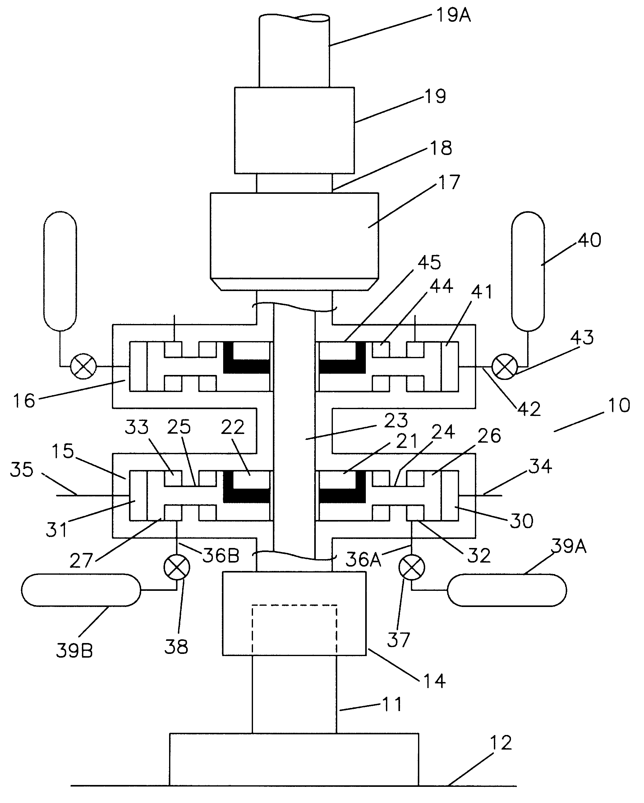
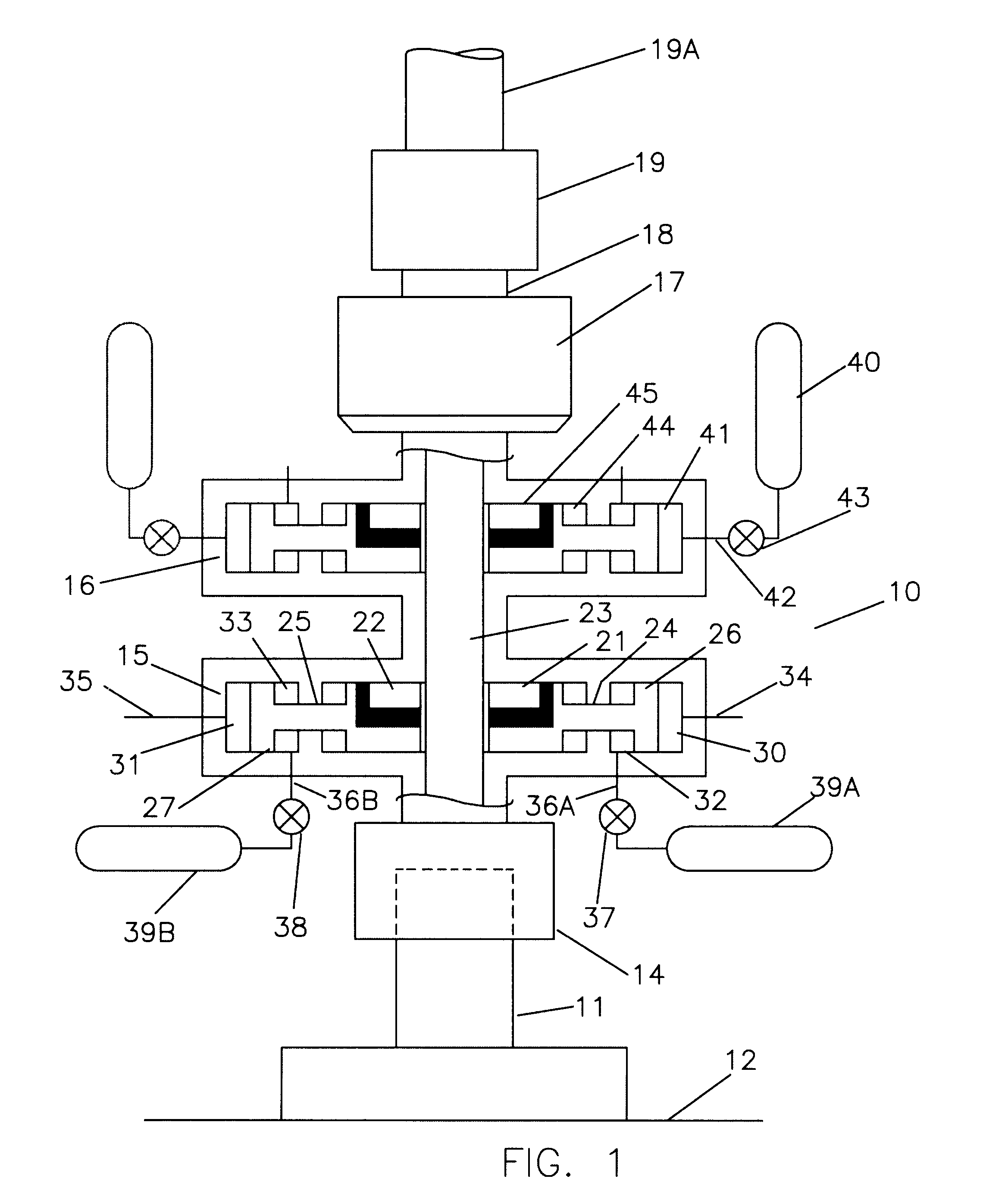
Referring now to FIG. 1, a blowout preventer (BOP) stack 10 is landed on a subsea wellhead system 11, which is supported above mudline 12. The BOP stack 10 is comprised of a wellhead connector 14 which is typically hydraulically locked to the subsea wellhead system 11, multiple ram type blowout preventers 15 and 16, an annular blowout preventer 17 and an upper mandrel 18. A riser connector 19, and a riser 19a to the surface are attached for communicating drilling fluids to and from the surface.

Blowout preventer 15 includes a body 20, rams 21 and 22 for moving into the vertical bore 23 for sealing, rods 24 and 25, pistons 26 and 27, outer chamber 30 and 31, and inner chambers 32 and 33. Lines 34 and 35 vent the outer chambers 30 and 31 to the seawater. Lines 36a and 36b communicate the inner chambers 32 and 33 with low pressure chambers 39a and 39b thru valves 37 and 38. If the valves 37 and 38 are opened, the differential pressure between the seawater pressure in outer chambers 30 a...


PUM


Abstract

An accumulator for use in deepwater operational and control systems which uses a differential between a high pressure ambient pressure source such as sea water pressure and a low pressure source such as a chamber holding vacuum or atmospheric pressure to provide storage and delivery of hydraulic power for operation of equipment.

Description

BACKGROUND OF THE INVENTIONThe field of this invention of that of deepwater accumulators for the purpose of providing a supply of pressurized working fluid for the control and operation of equipment. The equipment is typically blowout preventers (BOP) which are used to shut off the well bore to secure an oil or gas well from accidental discharges to the environment, gate valves for the control of flow of oil or gas to the surface or to other subsea locations, hydraulically actuated connectors and similar devices. The fluid to be pressurized is typically an oil based product or a water based product with added lubricity and corrosion protection.Currently accumulators come in three styles which operate on a common principle. The principle is to precharge them with pressurized gas to a pressure at or slightly below the anticipated minimum pressure required to operate equipment. Fluid can be added to the accumulator, increasing the pressure of the pressurized gas and the fluid. The flui...

Claims


Application Information

Patent Timeline
Patent Type & Authority Patents(United States)
IPC IPC(8): E21B33/03E21B33/035
CPCE21B33/0355E21B34/16F15B1/24F15B21/006F15B2201/31F15B2201/32F15B2201/40
Inventor BAUGH, BENTON F.
Owner BAUGH BENTON F
Why Eureka
Try Eureka