Friction clutch with low disengaging force

a friction clutch and low disengaging force technology, applied in the direction of friction clutches, mechanical actuated clutches, clutches, etc., can solve the problems of inconvenient arrangement, cancellation of declutching assistance, and the possibility of obtaining as much assistan

Inactive Publication Date: 2001-03-20
VALCO SA
View PDF21 Cites 7 Cited by
  • Summary
  • Abstract
  • Description
  • Claims
  • Application Information

AI Technical Summary

Problems solved by technology

During the declutching travel it is not possible to obtain as great an assistance as desired, the progressive action device reducing the load exerted by the diaphragm on the thrust plate during declutching.
The load curves of the progressive action device, when it is mounted within the friction member, and of the diaphragm, have shapes which do not make it possible to combine them in order to obtain high assistance for declutching, in particular if it is wished to respect declutching travels and forces compatible with the current declutching controls.
Moreover, the shape of the curve of the progressive action device changes, notably because of phenomena of encrustatio

Method used


Image

  • Friction clutch with low disengaging force
  • Friction clutch with low disengaging force
  • Friction clutch with low disengaging force

Examples


Embodiment Construction

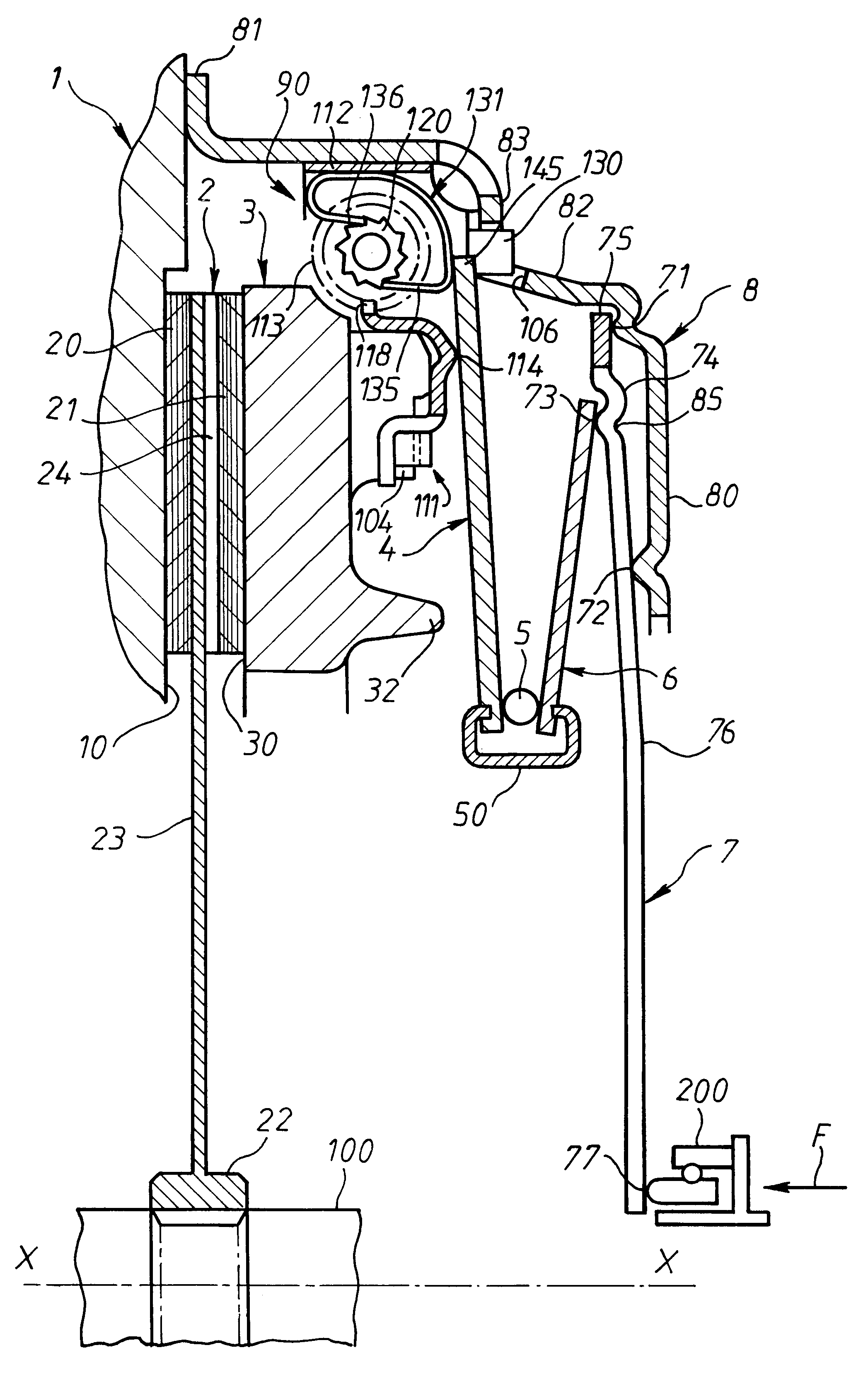
The clutch of the pushed type depicted in FIG. 1 is of the type described in the French patent application filed on Sep. 6, 1996 under the number 96 11 009, the description of which is to be considered as forming part of it. Overall, such a clutch includes a set of parts of annular shape, namely in axial succession a flywheel 1 for driving in rotation, for fixing the clutch to a first shaft, such as an input shaft, a clutch friction member 2 having at its outer periphery friction linings 20, 21 and at its inner periphery a hub 22 for connecting the clutch in rotation with a second shaft, such as an output shaft, a thrust plate 3, a first Belleville washer 4, a stop spring ring 5, a second Belleville washer 6 inclined in the opposite direction compared with the first Belleville washer 4, a declutching device 7 of annular shape, a cover 8 of annular shape having a bottom 80 overall of transverse orientation with a central hole and at its outer periphery fixing means 81 for fixing the ...


PUM


Abstract

A friction clutch for a motor vehicle having a clutching friction member and clutching mechanism with a cover and a clutch thrust plate. A resilient clutch member and disengaging gear is disposed between the rear surface of the thrust plate and the cover for moving the clutch thrust plate towards the cover. The clutch is provided with a wear adjustment device, a resilient servo member and a resilient smooth engagement member. The resilient servo member is mounted outside the clutching friction member. The load pressure feature combining the load pressure features of the resilient servo member and smooth engagement member globally follows the load pressure feature of an axially operating resilient clutching member.

Description

The present invention concerns friction clutches with low declutching force, notably for motor vehicles.DESCRIPTION OF THE RELATED ARTAs is known, in a conventional clutch interposed between input shaft and an output shaft, a diaphragm bears on the bottom of a cover, fixed to a flywheel driving in rotation, in order to move a thrust plate in the direction of the said flywheel, forming a reaction plate, in order to grip the friction linings of a clutch friction member between the said thrust and reaction plates.The driving flywheel is fixed to a first shaft, such as an input shaft, whilst the clutch friction member has at its inner periphery a hub for fixing it, with respect to rotation, to a second shaft, such as an output shaft.The clutch is therefore normally engaged, or clutched, with transmission of torque between the input and output shafts.In order to disengage, or declutch, the clutch, it is necessary, by means of a clutch release bearing, to act axially by pushing, in the ca...

Claims


Application Information

Patent Timeline
IPC IPC(8): F16D13/58F16D13/75
CPCF16D13/585F16D13/757F16D2013/581
Inventor BACHER, MICHELTHIRTON DE BRIEL, JACQUESGRATON, MICHAELDALBIEZ, ANDREBLARD, MICHELMINEREAU, HUGUES
Owner VALCO SA
Why Eureka
Try Eureka