
Surgical drill guide

Inactive Publication Date: 2001-04-03
LAB ENG & MFG
View PDF16 Cites 180 Cited by
  • Summary
  • Abstract
  • Description
  • Claims
  • Application Information

AI Technical Summary

Benefits of technology

Still another object of this invention is to provide a surgical drill guide that provides separate controls for advancing a guide tube toward a bone and locking the guide tube in position after it contacts the bone.
Still another object of this invention is to provide a surgical drill guide that provides separate controls for advancing a guide tube toward a bone and locking the guide tube in position after it contacts the bone and that facilitates manufacture.

Problems solved by technology

It appears possible to produce such a rotation inadvertently so that the ability of the mechanism to hold the guide tube against the bone becomes unreliable.

Method used


Image

  • Surgical drill guide
  • Surgical drill guide
  • Surgical drill guide

Examples


Embodiment Construction

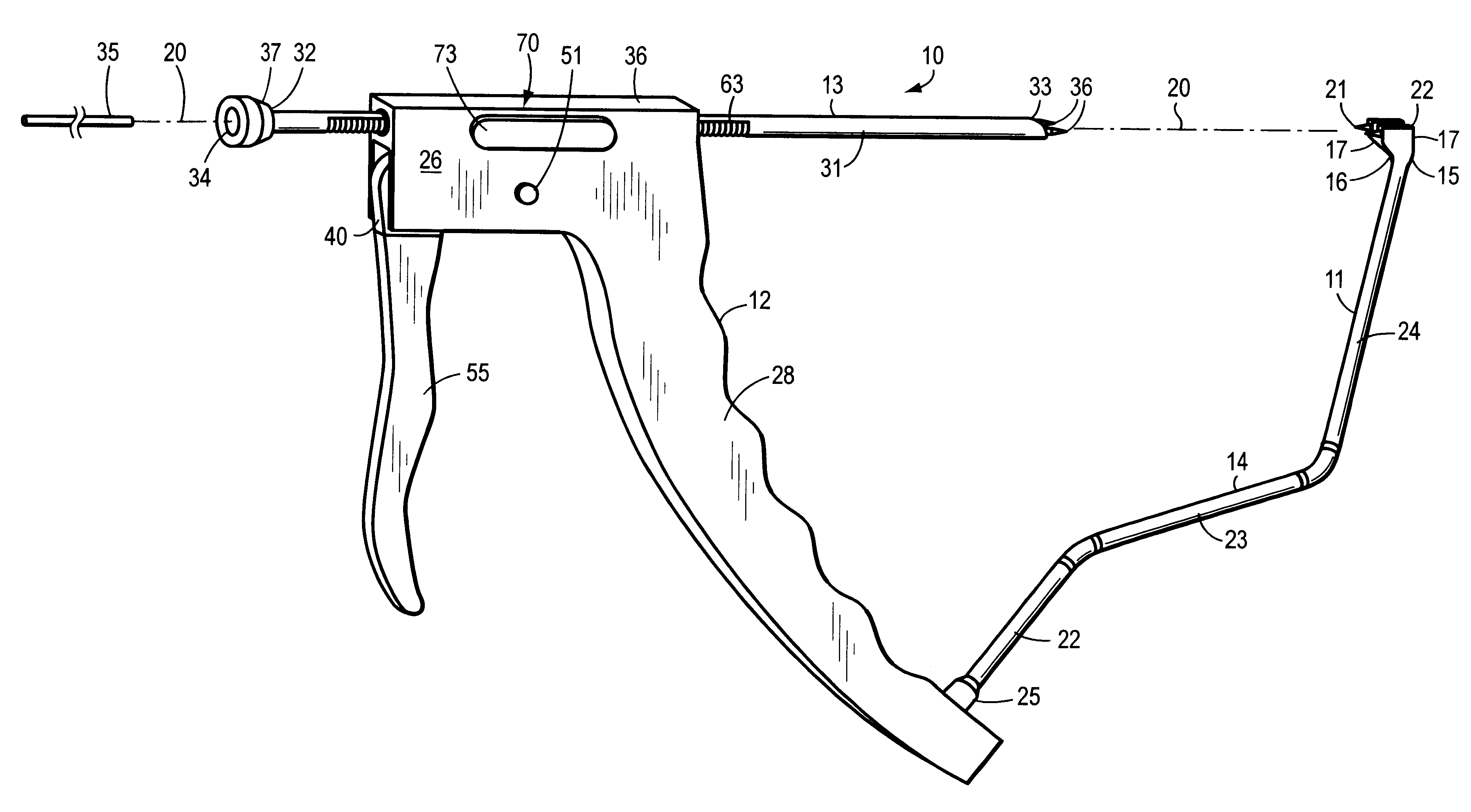
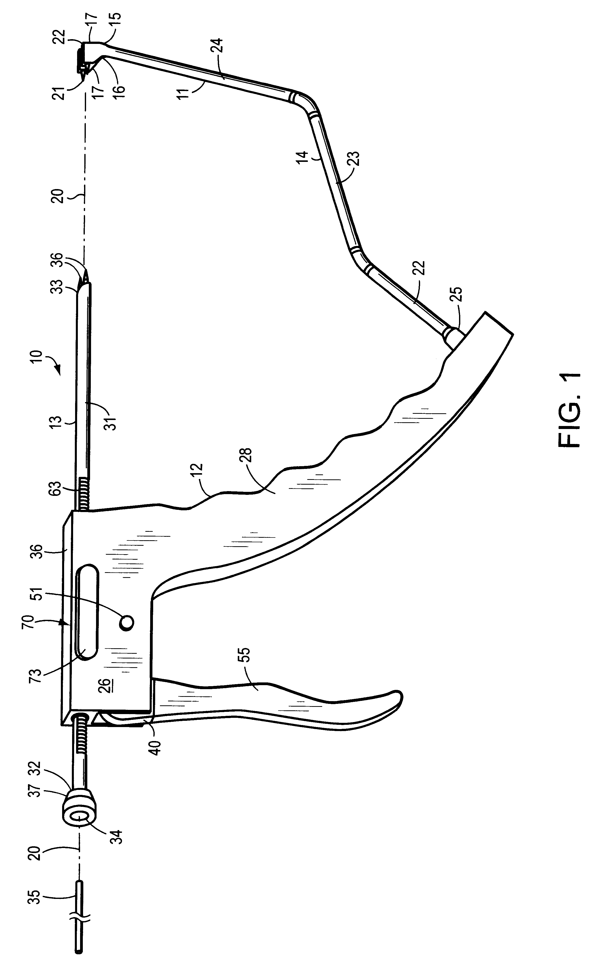
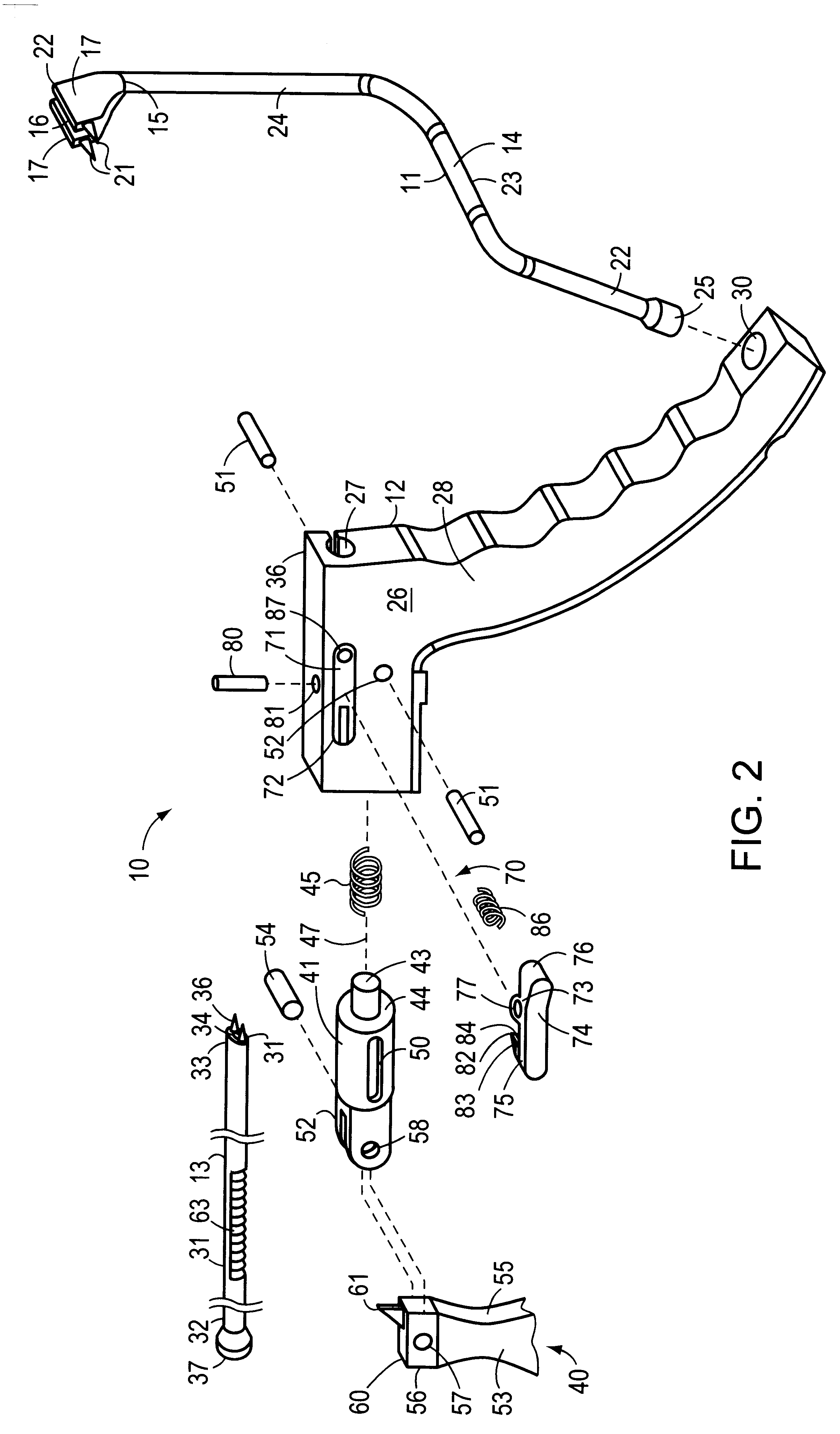
FIGS. 1 and 2 depict a surgical drill guide 10 constructed in accordance with this invention. The three main components of this structural drill guide 10 include a probe 11, a main body 12 and a guide tube 13.

The probe 11 includes an arm 14 that extends from the main body 12 and terminates as a target 15 at the free end of the probe 11. The target 15 includes a yoke 16 with bifurcated yoke arms 17 that extend from the probe. The bifurcation lies on an axis 20 along which the guide tube 13 extends so the guide can pass through the target 15. Each of the yoke arms 17 terminates in a tip 21 that faces the handle 12.

In this specific embodiment the arm 14 comprises three offset sections 22, 23 and 24 that extend from a base component 25. This specific shape is shown by way of example only. It will be apparent that other shapes that position the target 15 on the axis 20 and that allow the target 15 to be positioned in a patient will be acceptable.

Still referring to FIGS. 1 and 2 and the m...


PUM


Abstract

A surgical drill guide for directing a guide tube toward a target. The guide tube has first and second sets of teeth extending along an exterior surface thereof. A through passage in an operating mechanism housing receives the guide tube. A first actuator or guide tube advancing mechanism uses a ratchet and pawl mechanism to advance the guide tube distally. A guide tube locking mechanism, that includes another ratchet and pawl mechanism prevents any unwanted proximal motion by providing a releasable lock against any unwanted proximal motion of the guide tube during use.

Description

1. Field of the InventionThis invention generally relates to surgical drill guides and more specifically to an improved surgical drill guide that provides positive position control of a drill guide tube, particularly during arthroscopic surgical procedures.2. Description of Related ArtSurgical drill guides are well known in the art. They are very useful in enabling a surgeon to locate a drill guide tube with accuracy relative to adjacent anatomical structures. Generally these drill guides include a housing with a passage for a guide tube that extends along a guide tube axis. A handle portion of the surgical drill guide carries both the housing and a probe with a target end. The probe positions the target end at a location on a bone that intersects the guide tube axis. Generally some mechanism associated with the housing enables the guide tube to move along the axis into contact with the bone so the bone lies on a line between the distal end of the guide tube and the target. Once pos...

Claims


Application Information

Patent Timeline
IPC IPC(8): A61B17/17A61B17/16A61B17/90
CPCA61B17/1714
Inventor BESTER, LEON W.
Owner LAB ENG & MFG
Learn More