Linear/rotary electromagnetic device

a technology of electromagnetic devices and rotating shafts, applied in the direction of dynamo-electric converter control, multiple dynamo-motor starters, applications, etc., can solve the problems of heavy, complicated, and difficult conventional motor arrangements to achieve such motion, and achieve substantial disadvantages for robotic applications

Inactive Publication Date: 2001-04-03
TRITEX
View PDF2 Cites 49 Cited by
  • Summary
  • Abstract
  • Description
  • Claims
  • Application Information

AI Technical Summary

Benefits of technology

FIG. 1 is a side elevational view, partially in cross-section and partially cut-away, of an electromagnetic device according to a first embodiment of the present invention.
FIG. 2 is a side elevational view, partially in cross-section and partially cut-away, of an electromagnetic device according to a second embodiment of the present invention.
FIG. 3 is a side elevational view, partially in cross-section and partially cut-away, of an electromagnetic device according to a third embodiment of the present invention.
FIG. 4 is a side elevational view, partially in cross-section and partially cut-away, of an electromagnetic device according to a fourth embodiment of the present invention.

Problems solved by technology

Conventional motor arrangements to accomplish such motion are often complicated and heavy, a substantial disadvantage for robotics applications.

Method used


Image

  • Linear/rotary electromagnetic device
  • Linear/rotary electromagnetic device
  • Linear/rotary electromagnetic device

Examples


first embodiment

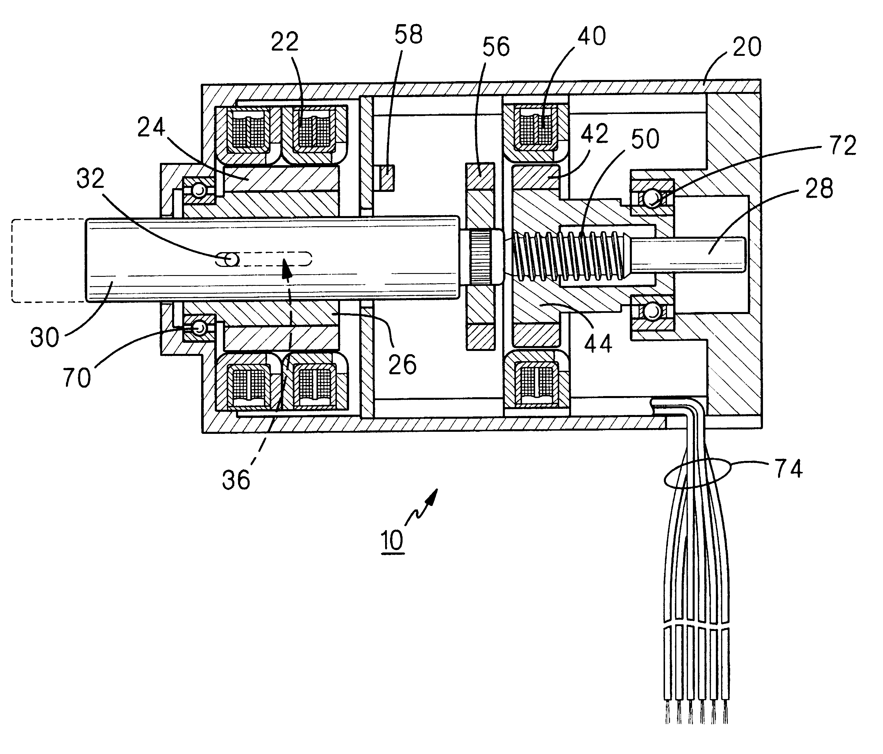
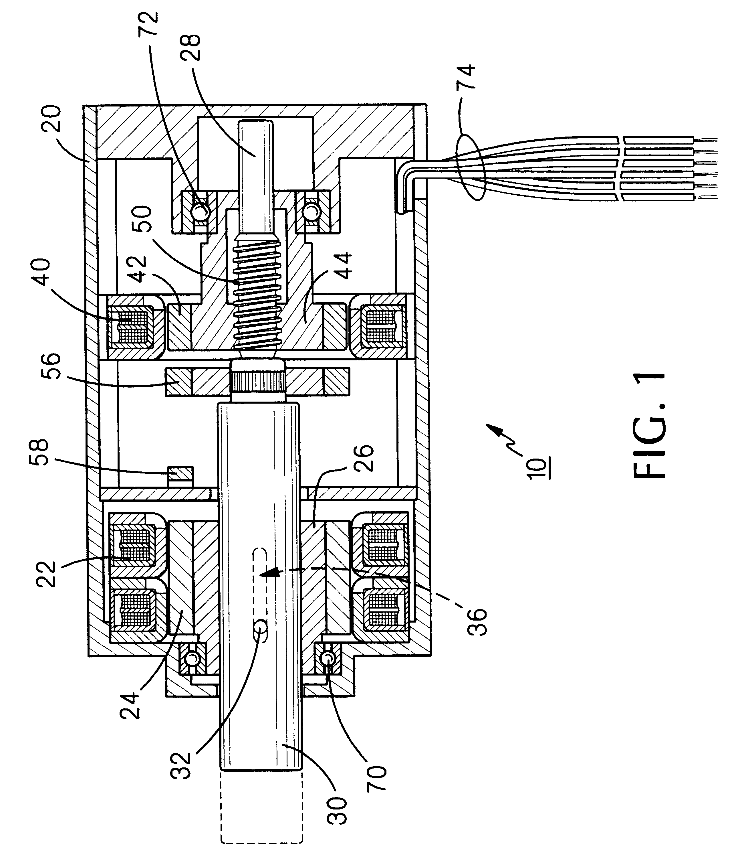
FIG. 1 illustrates a linear / rotary electric motor, constructed according to the present invention, the motor being generally indicated by the reference numeral 10. Motor 10 includes a housing 20 having an annular stator structure 22 fixedly mounted therein in magnetic interacting relationship with an annular permanent magnet 24 fixedly mounted on an annular bushing 26, the latter two elements comprising a motor rotor. A shaft 28 extends coaxially through housing 20 and includes a cylindrical portion 30 extending coaxially through bushing 26. Shaft 28 is secured against rotation relative to bushing 26 by means of a pin 32 extending through and fixedly attached to the bushing and extending through cylindrical portion 30. To permit axial movement of shaft 28 relative to bushing 26, pin 32 extends through an axially extending slot 36 defined through bushing 26.

Housing 20 also includes fixedly mounted therein a second annular stator 40 magnetically interacting with an annular permanent m...

second embodiment

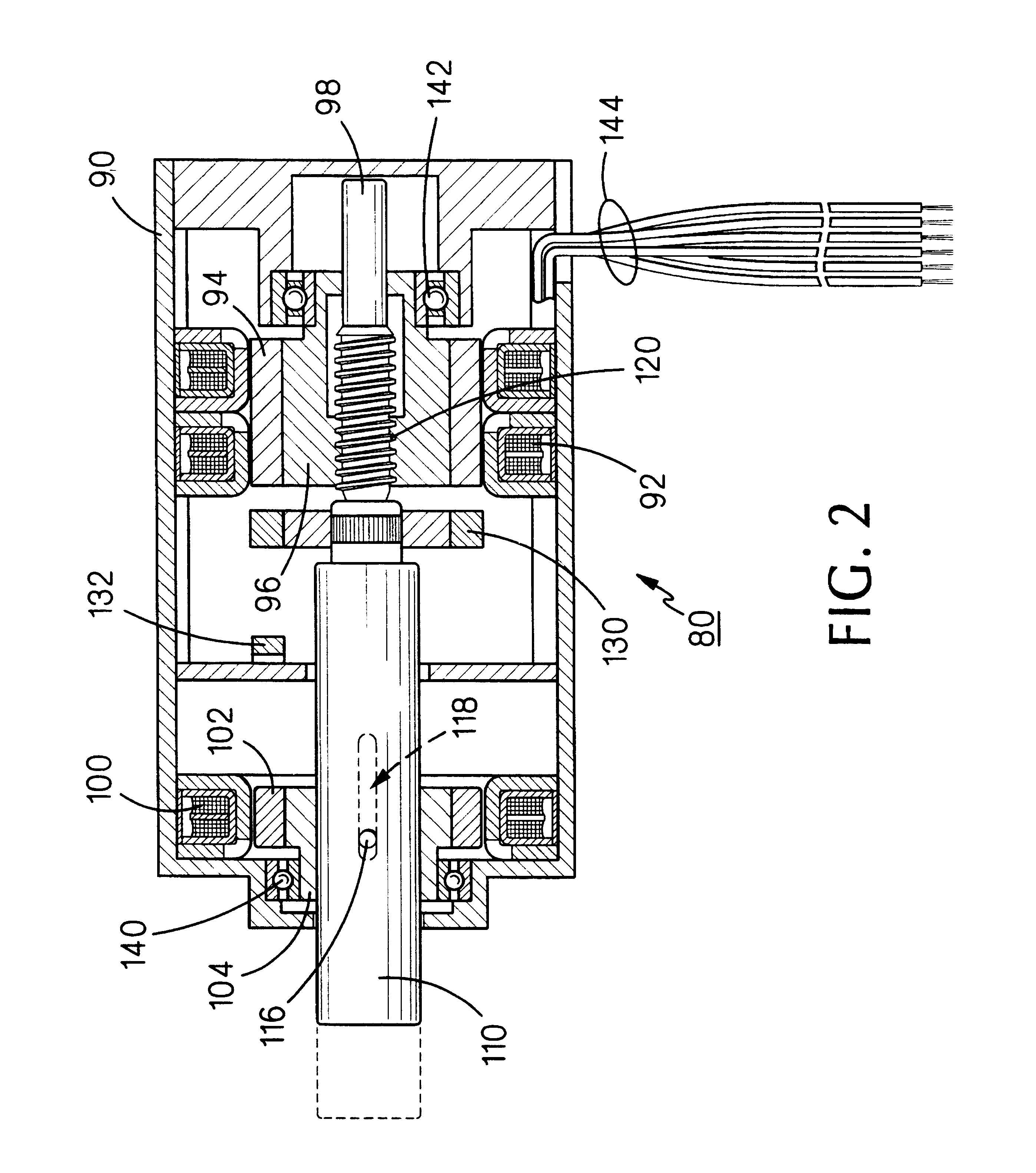
FIG. 2 illustrates a linear / rotary electric motor constructed according to the present invention, the motor being generally indicated by the reference numeral 80. Motor 80 includes a housing 90 having an annular stator structure 92 fixedly mounted therein in magnetic interacting relationship with an annular permanent magnet 94 fixedly mounted on an annular, internally threaded bushing 96, the latter two elements comprising a motor rotor.

Housing 90 also includes fixedly mounted therein a second annular stator 100 magnetically interacting with an annular permanent magnet 102 fixedly mounted on an annular bushing 104, the second stator and the permanent magnet comprising an electromagnetic brake. A shaft 98 extends coaxially through housing 90 and includes a cylindrical portion 110 extending coaxially through bushing 104. Shaft 98 is secured against rotation relative to bushing 104 by means of a pin 116 extending through the bushing and through and fixedly attached to cylindrical porti...

third embodiment

FIG. 3 illustrates a linear / rotary electric motor, constructed according to the present invention, the motor being generally indicated by the reference numeral 20'. Since motor 20' is a variation of motor 20 (FIG. 1), the common elements thereof are given primed reference numerals and reference should be made to FIG. 1 for a description of the elements and the operation thereof to the extent not described with reference to FIG. 3.

The differences between motor 20 and motor 20' is that, in the latter, permanent magnet 56 (FIG. 1) has been eliminated and Hall cell 58 is triggered when approached by permanent magnet 24' of rotor 24' / 26'. Also, motor 20' includes a return spring 150 disposed between bushing 26' and bearing 70' to return shaft 28' to its home position. Return spring 150 may not be required if motor 20' is operating in a vertical position.


PUM


Abstract

In a preferred embodiment, a linear/rotary electromagnetic device, including: a housing (20); first and second stators (22 and 40) disposed in the housing, first and second rotors (24/26 and 42/44) disposed in the housing and magnetically interacting, respectively, with the first and second stators; the first stator and the first rotor comprising a rotary motor; the second stator and the second rotor comprising an electromagnetic brake; a shaft (28) extending through a portion of the housing and axially through the first and second rotors, the shaft having a threaded portion (50) extending through a complementary threaded portion (44) of one of the first and second rotors; whereby; when the electromagnetic brake is locked and the rotary motor is rotated in a first direction, the shaft will move axially in a first direction; when the electromagnetic brake is locked and the rotary motor is rotated in the second direction, the shaft will move axially in a second direction; and when the electromagnetic brake is released and the rotary motor is rotated, the shaft will rotate with the rotary motor.

Description

The present invention relates to electromagnetic devices generally and, more particularly, but not by way of limitation, to a novel electromagnetic device which selectively provides rotary and / or linear motion at a single output shaft.In certain applications, it is desirable to have a shaft which may selectively rotate and / or reciprocate. Such an application, for example, is in the robotic picking and placing of components where it may be required to axially move a component to an insertion position and then rotate the component to screw it in place. Conventional motor arrangements to accomplish such motion are often complicated and heavy, a substantial disadvantage for robotics applications. Another type of application requiring a shaft which may selectively rotate and / or reciprocate is in the precise control of laparoscopic and other such medical instruments.In either type of application, it is frequently required that the linear motion be locked while rotary motion takes place. F...

Claims


Application Information

Patent Timeline
Patent Type & Authority Patents(United States)
IPC IPC(8): B25B21/00B25J9/12H02K7/10H02K7/06H02K7/106A61B19/00A61B17/00H02K11/00
CPCB25B21/00B25J9/123H02K7/06H02K7/106A61B17/00234A61B19/22H02K11/00H02K2201/18H02K16/00A61B34/70
Inventor KOWALSKI, KEITHPALMERO, ALBERT
Owner TRITEX
Why Eureka
Try Eureka