Flow velocity measuring unit

a technology of flow velocity and measuring unit, which is applied in the direction of instruments, liquid/fluent solid measurement, volume measurement, etc., can solve the problems of reducing the accuracy of measurement and the inability of known apparatuses to ensure sufficient measuremen

Inactive Publication Date: 2001-04-10
DEREVYAGIN ALEXANDR MIKHAILOVICH
View PDF8 Cites 8 Cited by
  • Summary
  • Abstract
  • Description
  • Claims
  • Application Information

AI Technical Summary

Problems solved by technology

However, the known apparatus does not ensure sufficiently accurate measurement because of the possibility of contamination of elements of the optical unit with impurities in the medium being studied.
However, this known apparatus does not prevent contamination of elements of the optical unit with impurities of the medium being studied, and this reduces the accuracy of measurement.

Method used


Image

  • Flow velocity measuring unit
  • Flow velocity measuring unit

Examples


Embodiment Construction

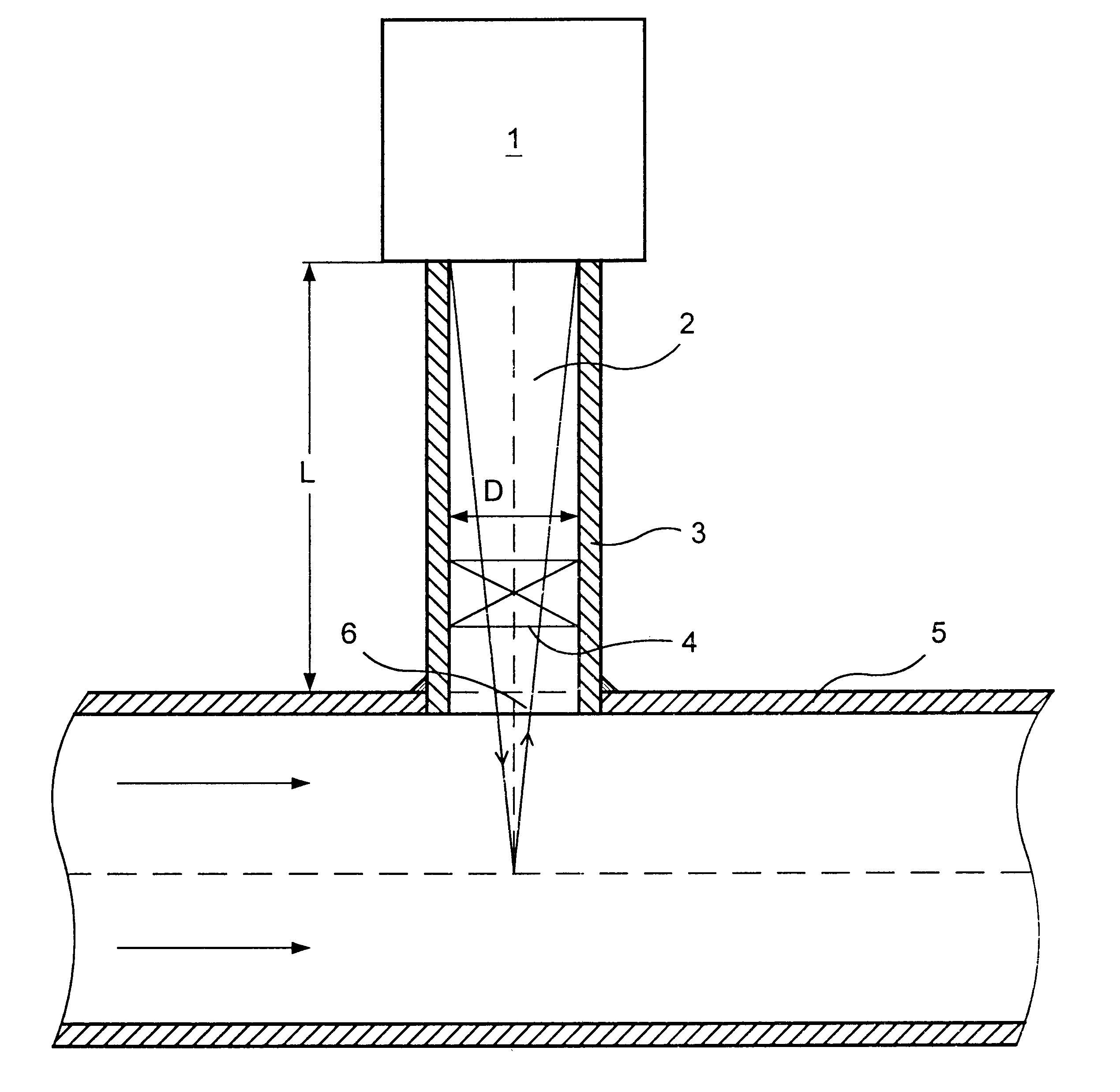
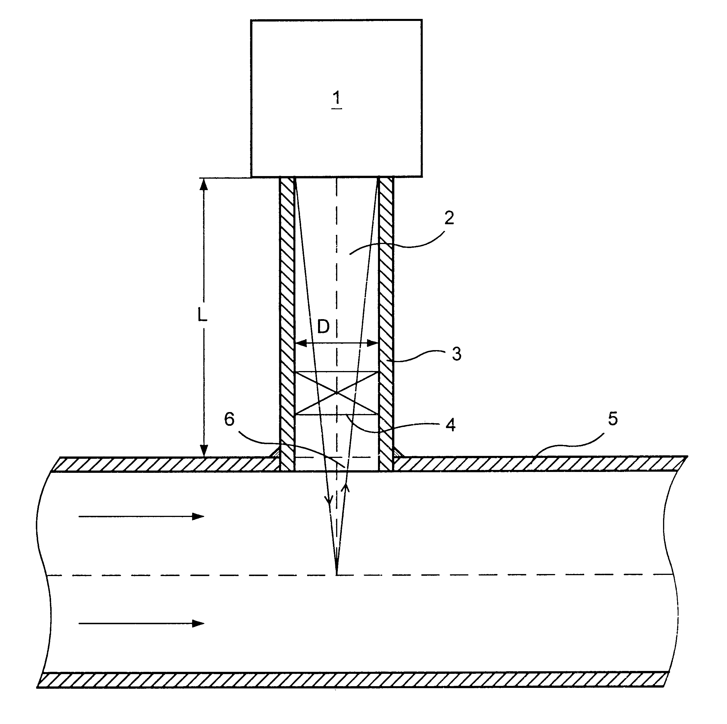
A flow velocity measuring unit comprises an optical unit 1 with a laser, photodetector and recorder (not shown in the drawing), and a gravitational filter 2 made in the form of a pipe 3 in which a shut-off cock 4 is mounted.

One end of the pipe 3 of the gravitational filter 2 is mounted on the top side of a pipeline 5 in an aperture 6 and is secured, for example, by means of welding.

The optical unit 1 is secured on the other end of the pipe 3 by means of, for example, a threaded connection.

The length L of the pipe exceeds by more than three times its diameter D, and the apparatus operates in the following manner.

When the apparatus is turned on with the shut-off cock 4 open, measurement of the flow velocity of a medium, for example, gas, begins.

A laser beam, passing through the pipe 3 of the gravitational filter 2 falls on the gas flow moving in the pipeline 5 and reflected light from gas particles is received by the photodetector of the optical unit 1. A converted signal from the opt...


PUM

PropertyMeasurementUnit
flow velocity measuringaaaaaaaaaa
flow velocityaaaaaaaaaa
lengthaaaaaaaaaa

Abstract

A Doppler flow velocity measuring unit wherein an optical unit including a laser and a photodetector is removably mounted on a pipeline is disclosed. The optical unit is attached to a pipe that is affixed to the pipeline at right angles to the flow in the pipeline. The pipe includes a shutoff valve that closes the pipe, permitting the optical unit to be removed from the pipeline.

Description

The invention relates to the field of control and measuring technology, and more exactly, to a unit for measuring the flow of continuous optically transparent mediums for example, optical flow velocity measuring units using Doppler methods on gases, liquids, etc.DESCRIPTION OF RELATED ARTA flow velocity measuring unit is known which comprises an optical unit including a laser and a photodetector (SU No. 1053005, 1982).However, the known apparatus does not ensure sufficiently accurate measurement because of the possibility of contamination of elements of the optical unit with impurities in the medium being studied.A flow velocity measuring unit is known which comprises an optical unit including a laser and a photodetector (SU No. 48 836, 1973).However, this known apparatus does not prevent contamination of elements of the optical unit with impurities of the medium being studied, and this reduces the accuracy of measurement.The principal object at the base of the invention is to provi...

Claims


Application Information

Patent Timeline
Patent Type & Authority Patents(United States)
IPC IPC(8): G01F15/00G01F15/12G01P5/00
CPCG01F15/12G01P5/00
Inventor DEREVYAGIN, ALEXANDR MIKHAILOVICH
Owner DEREVYAGIN ALEXANDR MIKHAILOVICH
Why Eureka
Try Eureka