Roller massaging mechanism and massaging apparatus incorporating the same

a massaging mechanism and roller technology, applied in the field of roller massaging mechanism and massaging apparatus incorporating the same, can solve the problems of users' diversified needs, user's inability to vary the slanting direction of each roller relative to the rotary shaft, and easy loss of interest of users

Inactive Publication Date: 2001-04-10
DAITO ELECTRIC MACHINE IND
View PDF17 Cites 52 Cited by
  • Summary
  • Abstract
  • Description
  • Claims
  • Application Information

AI Technical Summary

Benefits of technology

In this case, though the massaging roller supported by the driven shaft portion receives pressure from the affected part, a braking member restrains the second shaft portion from rotating relative to the first shaft portion thereby preventing the collapse of the kneading or non-kneading position of the massaging rollers, hence allowing for a proper massage operation with the massaging rollers maintained in the kneading or non-kneading position properly.

Problems solved by technology

In the conventional roller massaging mechanism, however, the pair of right and left massaging rollers are fixed on the rotary shaft as slanted opposite to each other and, hence, the slanting direction of each roller relative to the rotary shaft cannot be varied, thus providing the kneading massage only.
Accordingly, the conventional massaging mechanism capable of performing only the kneading massage with the pair of right and left slanted massaging rollers cannot meet users' diversified needs and tends to let users lose their interest easily.
Although a variety of massaging apparatus performing various massaging operations as well as the kneading massage have been suggested, such massaging apparatus generally have a complicated structure in the drive system of massaging members or in the control program for performing various massaging operations and, hence, are large in size and expensive.

Method used


Image

  • Roller massaging mechanism and massaging apparatus incorporating the same
  • Roller massaging mechanism and massaging apparatus incorporating the same
  • Roller massaging mechanism and massaging apparatus incorporating the same

Examples


first embodiment

FIGS. 1 to 8 show the present invention.

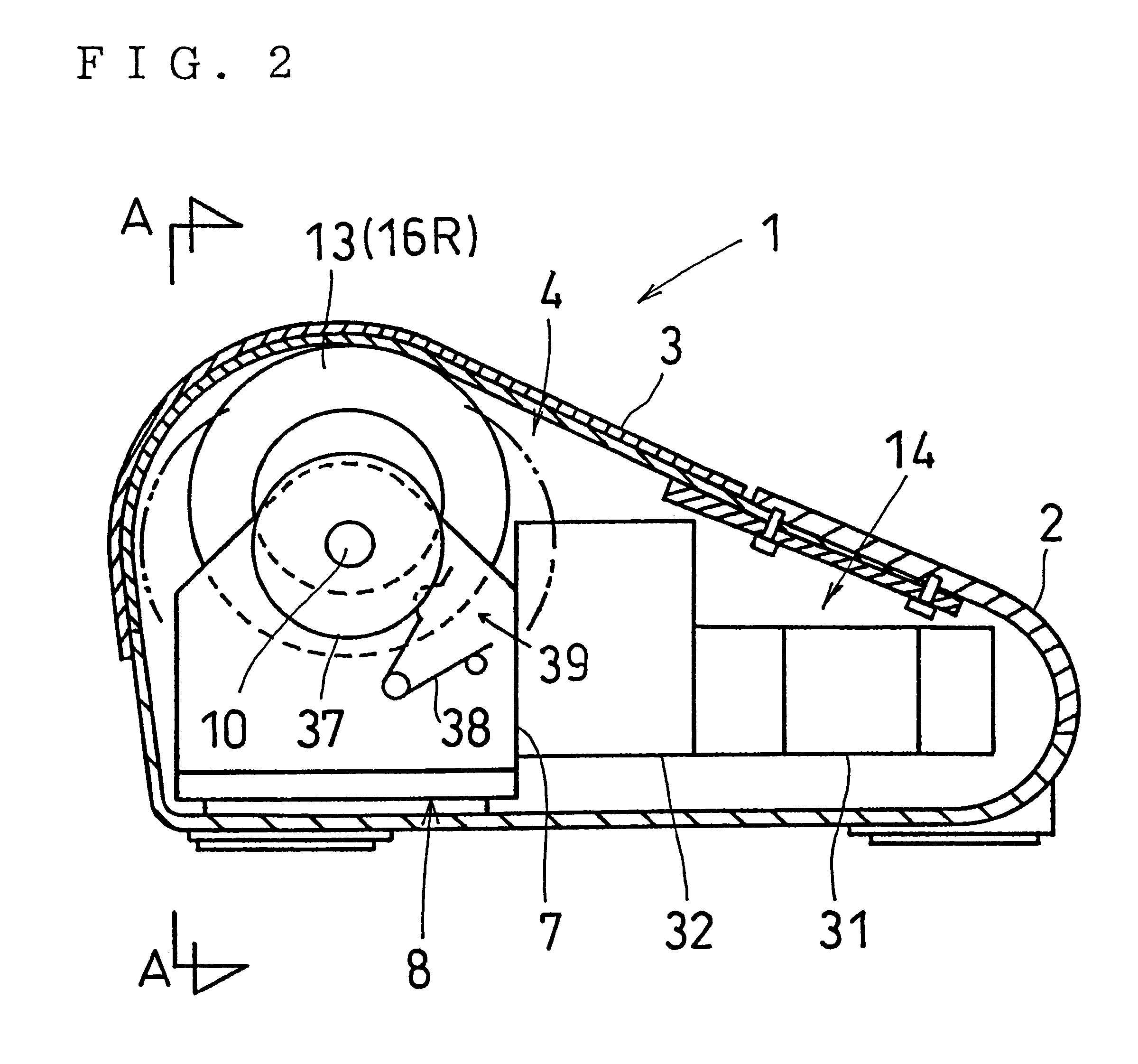
FIG. 3 illustrates an example of massaging apparatus 1 incorporating therein roller massaging mechanism 4 according to the present invention. The massaging apparatus 1 shown is of a stationary type which is relatively compact and flat.

This stationary-type massaging apparatus 1 includes a stationary-type casing 2 defining an opening 2A oriented upwardly, and the roller massaging mechanism 4 housed in the casing 2, the opening 2A being closed with a flexible cover member 3 formed of a stretch fabric or the like. The massaging apparatus 1 can be used by, for example, being placed under the back, waist, thighs or calves of a human lying on his or her back, or under the feet of a human sitting on a chair.

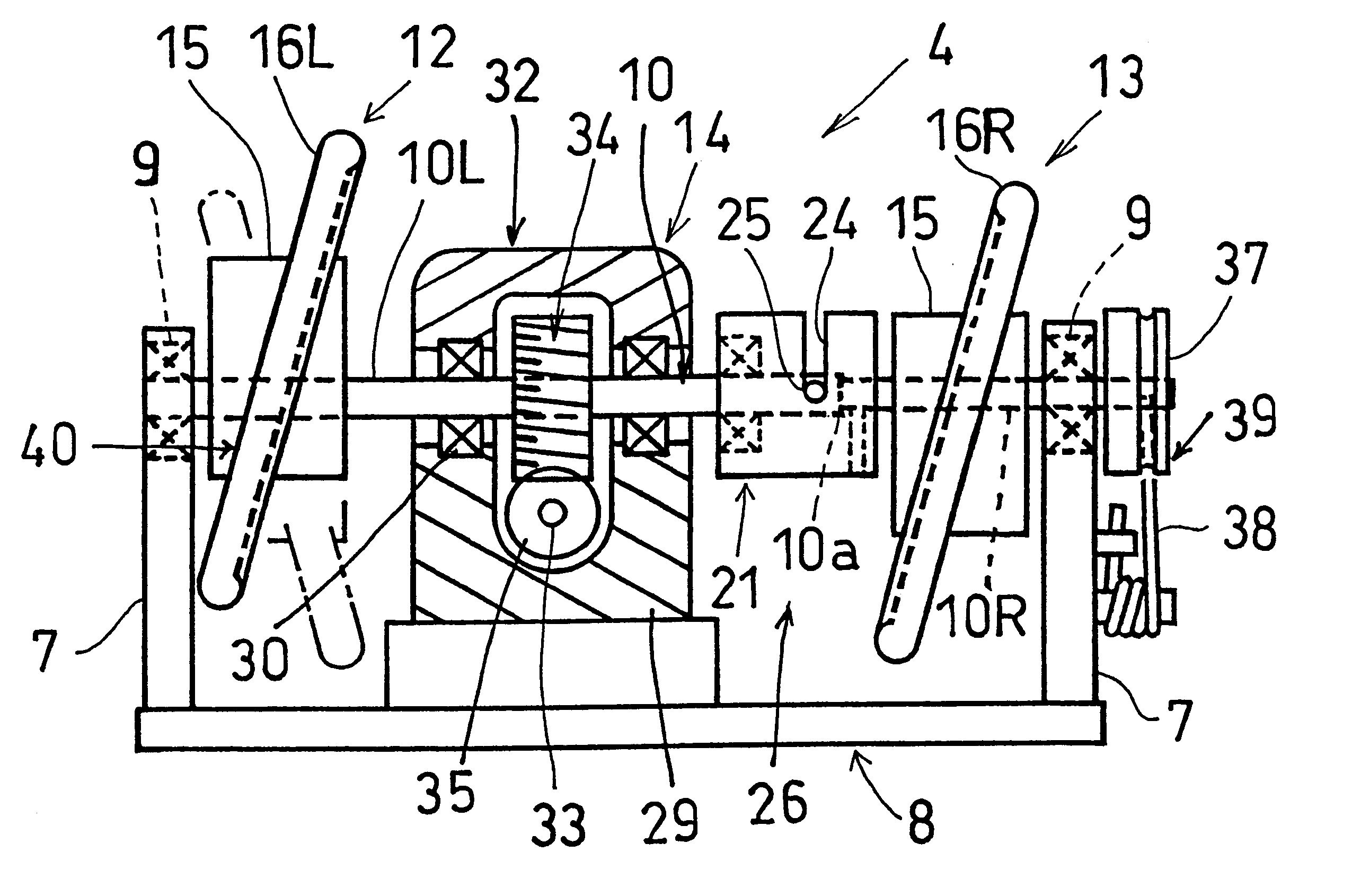
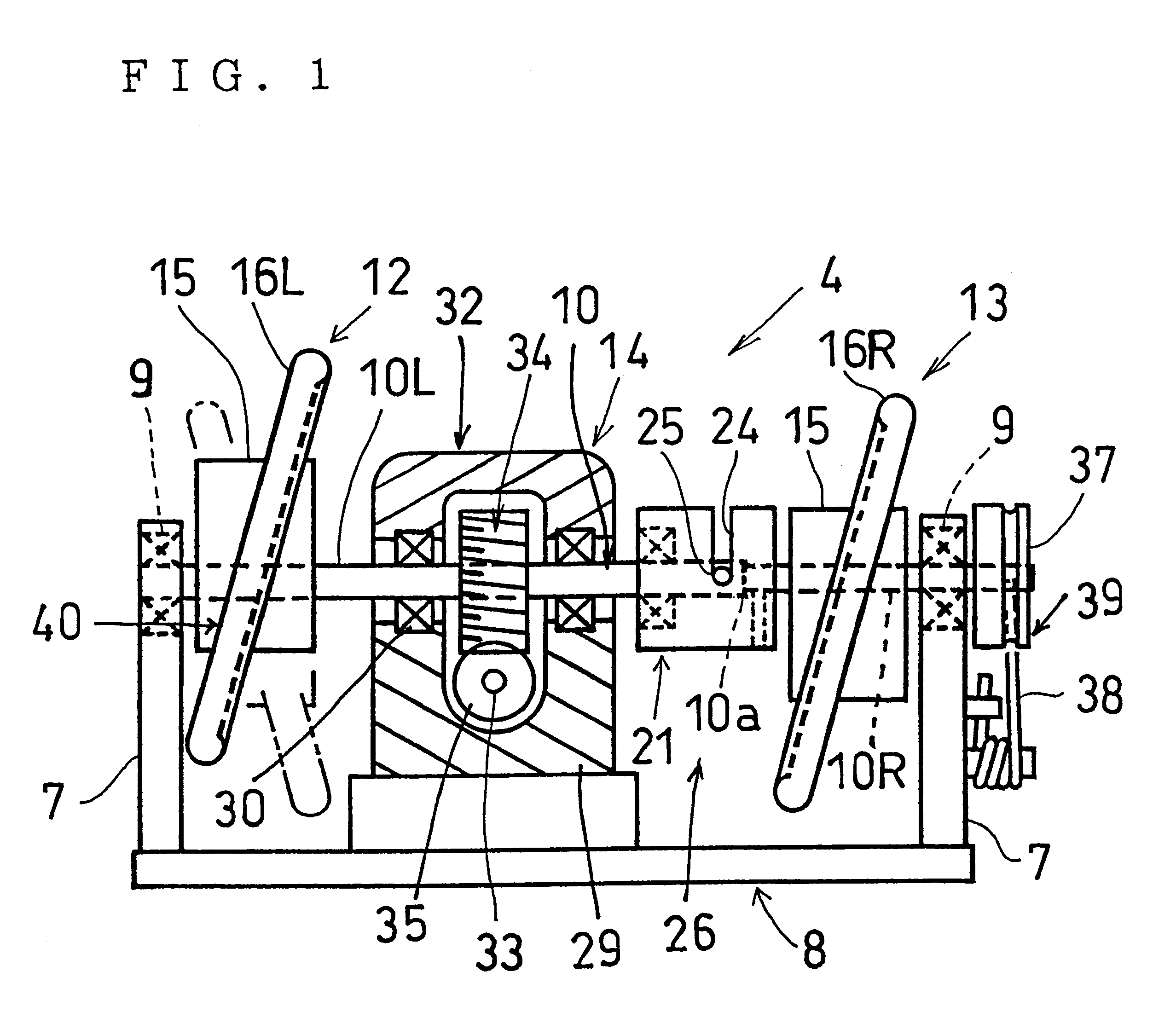
As shown in FIGS. 1 and 2, the roller massaging mechanism 4 includes a support frame 8 having at right and left ends thereof right and left support brackets 7,7 with a predetermined spacing therebetween, a rotary shaft 10 extending between and rota...

second embodiment

FIG. 9 illustrates the present invention.

This embodiment is a chair-type massaging apparatus 43 including a seat portion 41, a backrest portion 42 extending upwardly from an end portion of the seat portion 41, and the aforementioned roller massaging mechanism 4 shown in FIG. 1 and disposed within the backrest portion 42.

It should be noted that the roller massaging mechanism 4 may be incorporated also in the seat portion 41 or in a footrest (not shown) as well as in the backrest portion 42.

If shift means is provided for upwardly and downwardly shifting the roller massaging mechanism 4 disposed within the backrest portion 42, it is possible to massage a larger extent of a user's body from the occiput portion through the back to the waist.

third embodiment

FIGS. 10 and 11 illustrate the present invention.

This embodiment is a hand-carriable massaging apparatus 54 including a hand-carriable casing 53 having an opening 51 on a front side thereof (on the top side in FIG. 10) and grip portions 52 on right and left lateral sides thereof, and the roller massaging mechanism 4 disposed in the casing 53.

The casing 53 shown defines a pair of right and left openings 51,51 on the top side thereof through which the right and left massaging rollers 16R,16L project upwardly from the casing 53. The cover member 3 shown is divided into right and left separate ones for closing the openings 51,51, respectively.

As shown in FIG. 11, second brake means 40' employed in this embodiment comprises a ring spring 55 disposed on opposite sides of each massaging rollers 16R,16L. The ring spring 55 is inserted in a clearance between each sandwiching plate 15a, 15b and each massaging rollers 16R,16L to provide a friction resistance against the rotation of the rollers...


PUM


Abstract

A roller massaging mechanism of a type having a pair of right and left massaging rollers mounted on an intermediate portion of a rotary shaft in a slanted fashion relative to an axis of the rotary shaft, and includes a switching member for selectively switching the position of the pair of right and left massaging rollers into one of a kneading position where the pair of massaging rollers are slanted opposite to each other and a non-kneading position where the massaging rollers are slanted parallel with each other. When the massaging rollers are caused to assume the kneading position by the switching member, a kneading massage operation is performed, while when the massaging rollers are caused to assume the non-kneading position, a massage operation other than the kneading massage operation such as a finger pressure-like massage or a tapping massage is performed

Description

The present invention relates to a roller massaging mechanism capable of performing a variety of massaging operations for a human and massaging apparatus incorporating such mechanism.Conventional massaging apparatus incorporating a roller massaging mechanism include a bed-type one as described, for example, in Japanese Unexamined Patent Publication No. SHO 59-28963 and a relatively compact stationary-type one as described, for example, in Japanese Examined Patent Publication HEI No. 4-78307 or Japanese Unexamined Utility Model Publication No. HEI 2-109628.The bed-type massaging apparatus includes a roller massaging mechanism which is shiftable in the longitudinal direction of the bed. The massaging mechanism comprises a transversely extending rotary shaft capable of moving longitudinally of the bed, and a pair of right and left massaging rollers mounted on the rotary shaft as slanted relative to the axis of the rotary shaft, the rollers being slanted opposite to each other.The afore...

Claims


Application Information

Patent Timeline
Patent Type & Authority Patents(United States)
IPC IPC(8): A61H15/00A61H1/00A61H37/00
CPCA61H15/0078A61H2015/0035A61H2201/0138A61H2201/0142A61H2201/0149A61H2201/1427A61H2201/1669A61H2201/5066A61H7/007
Inventor SHIMIZU, NOBUZO
Owner DAITO ELECTRIC MACHINE IND
Why Eureka
Try Eureka