Vascular access port with elongated septum

a septum and vascular access technology, applied in the field of vascular access systems, can solve the problems of insufficient penetration force of the needle for a given septum, pain for patients, and necrosis of the tissue surrounding the implantation pocket,

Inactive Publication Date: 2001-04-10
CR BARD INC
View PDF36 Cites 321 Cited by
  • Summary
  • Abstract
  • Description
  • Claims
  • Application Information

AI Technical Summary

Problems solved by technology

This is quite painful to the patient and disruptive of the therapeutic process.
If the inadvertent withdrawal of the tip of the shaft of the hypodermic needle from the septum is not detected, however, fluids in the syringe associated with the hypodermic needle will not even enter the fluid reservoir of the vascular access port when infusion of those fluids is undertaken.
Necrosis of the tissue surrounding the implantation pocket will occur as a result, complicating therapeutic activities and frequently requiring the removal and reimplantation at another site of the entire vascular access system.
First, the needle penetration force for a given septum cannot be substantial, or the process of accessing the fluid reservoir of the associated vascular access port with the tip of the shaft of a hypodermic needle will be difficult for medical personnel and dangerous to the patient.
The inwardly directed forces imposed on an installed septum by the housing of a vascular access port must, however, not be so great that penetrating the septum with the tip of a hypodermic needle results in coring of the septum.
These particles can obstruct fluid flow through the outlet stem of the vascular access port, or if escaping through the outlet stem of the vascular access port, can become trapped in the cardiovascular system of the patient.
Nonetheless, continued coring eventually leads to various forms of septum failure that cannot be overcome by such inwardly directed forces.
The material continuity of the septum is increasingly compromised, resulting in crumbled areas of the septum matrix.
Eventually, leakage of fluid can be expected through the septum from the fluid reservoir in the vascular access port.
Once such fluid escapes to the exterior of the vascular access port, necrosis will occur of the tissue surrounding the subcutaneous pocket in which the vascular access port is implanted, causing consequences already described above.
The subcutaneous placement of a vascular access port makes it difficult to predict with precision the location in cross section of the septum of that vascular access port that will be penetrated by a hypodermic needle on any given occasion.
The use of a round septum to produce uniform properties in the installed septum does, however, have drawbacks.
It also reduces the chances that any given probe by the tip of the shaft of a hypodermic needle through the tissue of the patient at the implantation site will miss the septum entirely.
Missing the needle target area of the septum of vascular access port is a painful event for the patient.
It is an event that also presents major risks.
A large needle target area in the septum of a vascular access port also decreases the likelihood that the desirable repeated selective penetration of the septum by the tip of a hypodermic needle will inadvertently become concentrated over time in any small region of the septum.
The implantation of a vascular access port at these locations is not, however, entirely convenient for repeated ongoing therapy.
Correspondingly, greater is the potential for infection or for other complications.

Method used


Image

  • Vascular access port with elongated septum
  • Vascular access port with elongated septum
  • Vascular access port with elongated septum

Examples


Embodiment Construction

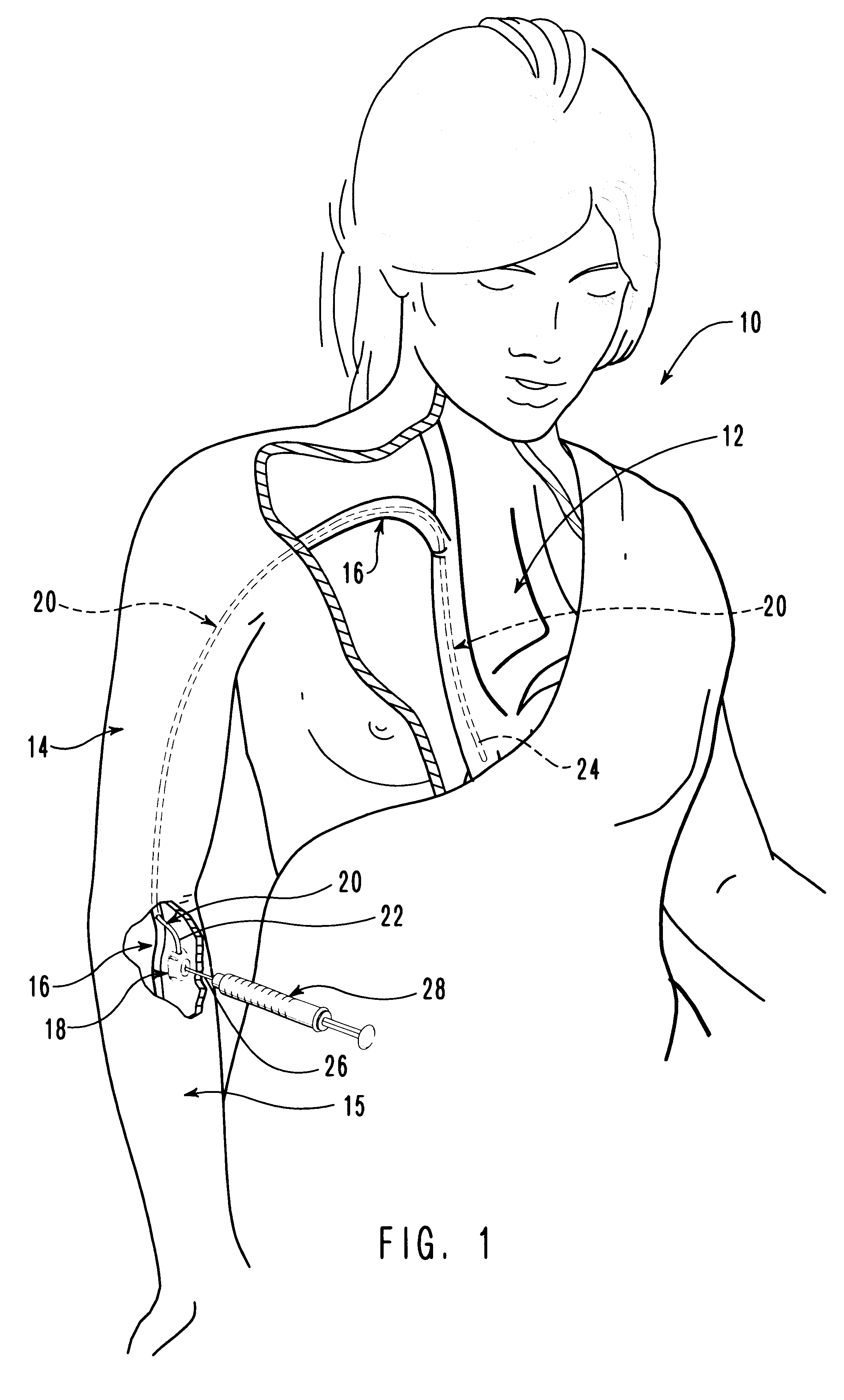
In FIG. 1, a patient 10 is shown having a chest 12, a right arm 14, and a forearm 15 associated therewith. A vein 16 extends from forearm 15 through arm 14 and into chest 12.

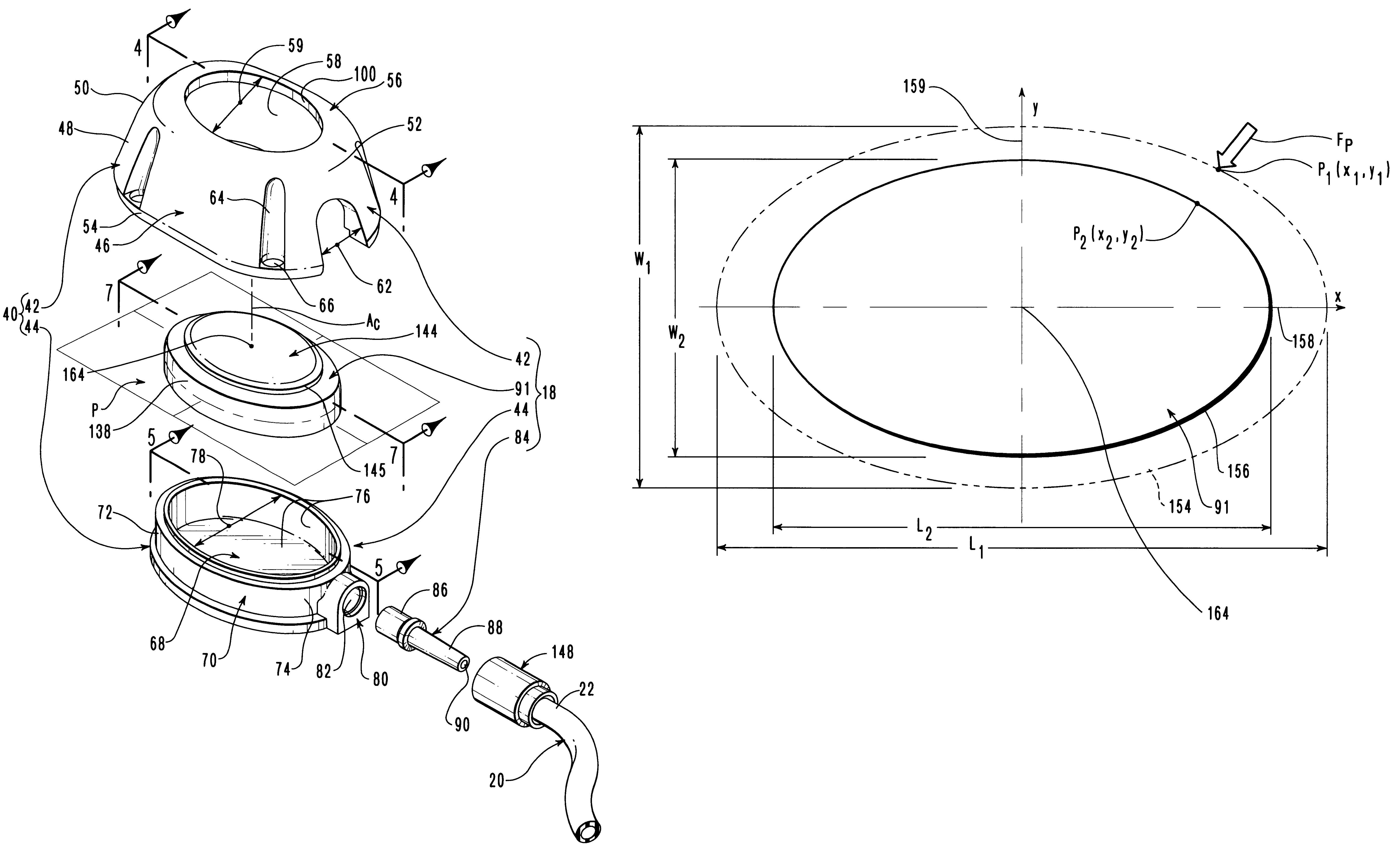
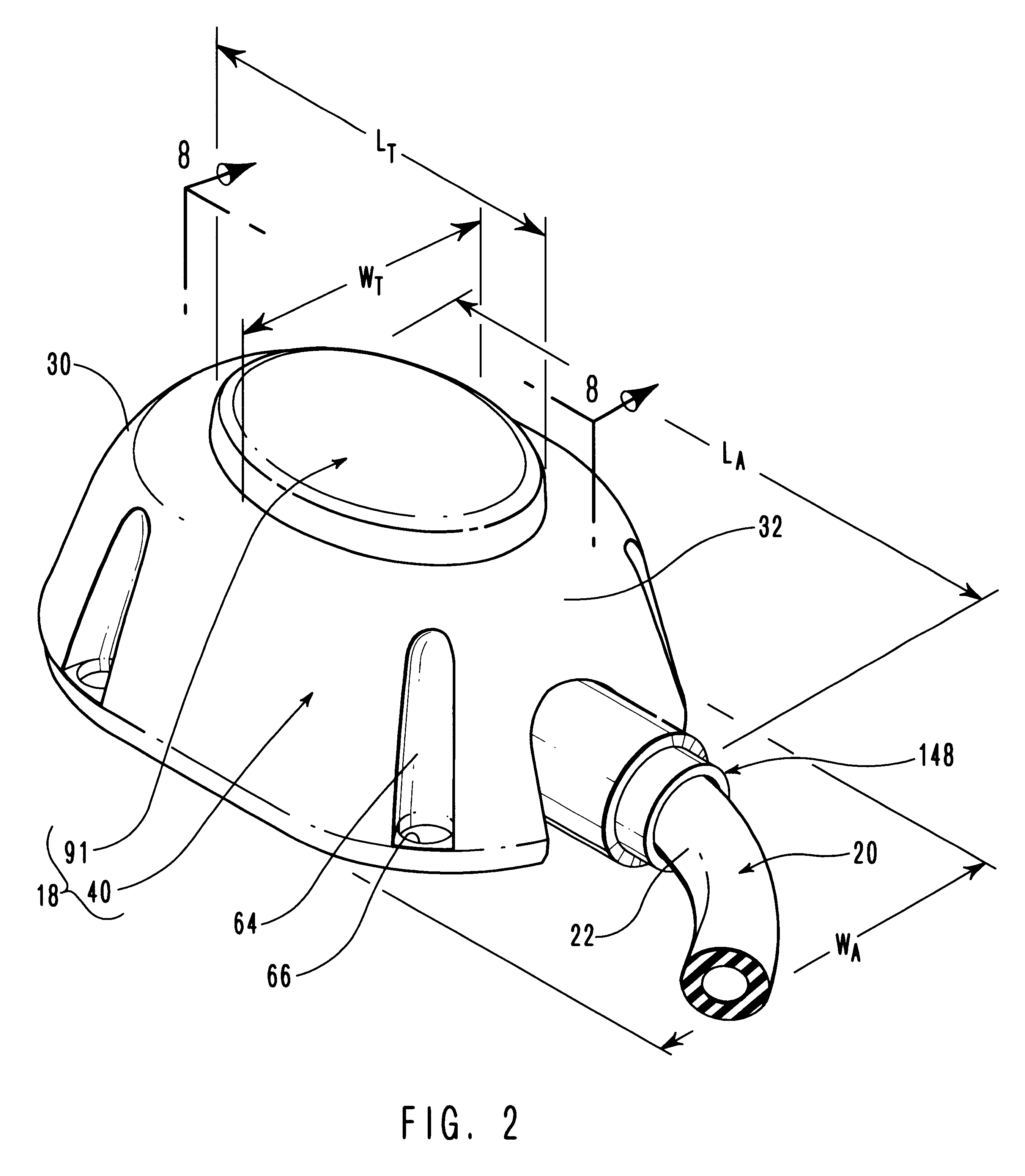
Subcutaneously implanted in forearm 15 of patient 10 is one embodiment of a vascular access port 18 incorporating teachings of the present invention. Also implanted with vascular access port 18 is an elongated, pliable vascular catheter 20 that is coupled at the proximal end 22 thereof to vascular access port 18. Catheter 20 enters vein 16 in the proximity of vascular access port 18 and extends within vein 16 from forearm 15, through arm 14, and into chest 12 of patient 10. The distal end 24 of catheter 20 has been advanced through vein 16 to a desired location within chest 12 of patient 10 near the heart thereof. Distal end 24 of catheter 20 is either open, or is provided with such pressure-sensitive valving as affords for S one-way or two-way fluid flow therethrough according to the intended use of vascular ac...


PUM


Abstract

An elongated access port has a needle-impenetrable housing enclosing a fluid reservoir. The housing includes a base having a floor with an upstanding encircling sidewall and a cap having a top wall with a depending encircling skirt. The skirt of the cap receives the sidewall of the base. An access aperture extends through the top wall of the cap to communicate with the fluid reservoir. The access aperture is encircled by a continuous rim having an elongated shape in the plane of the access aperture. The rim of the access aperture may be elliptical, oval, polygonal, or parabolic-ended. An elastomeric, needle-penetrable, generally planar septum is disposed in the access aperture with the periphery of the septum in sealing engagement with the rim of the access aperture. Prior to installation, the septum has a periphery with a cross section in the plane of the septum that is geometrically proportional to and larger than the shape of the access aperture. Installation causes the periphery of the septum to be displaced inwardly by the rim of the access aperture in a direction parallel to the plane of the septum. In view of the relative shapes of the rim of the access aperture and the periphery of the septum, this produces substantially uniform hydrostatic pressure in regions of the installed septum that are subjected in use of the access port to needle penetrations. Opposite faces of the periphery of the septum are urged toward each other between the cap of the housing and the top of the sidewall of the base of the housing.

Description

1. The Field of the InventionThe present invention relates to vascular access systems and, more specifically, to implantable vascular access ports for use in such systems.2. Background ArtImplantable vascular access systems are used extensively in the medical field to facilitate the performance of recurrent therapeutic tasks inside the body of a patient.Such a vascular access system generally includes an implantable vascular access port attached to the proximal end of a vascular catheter. A typical vascular access port has a needle-impenetrable housing that encloses a fluid reservoir that is accessible from the exterior of the access port through a needle-penetrable elastomeric septum. The vascular access port also includes an outlet stem, which projects from the housing and encloses a fluid passageway that communicates with the fluid reservoir. The distal end of the catheter is mechanically coupled to the vascular access port in fluid-tight communication with the fluid reservoir us...

Claims


Application Information

Patent Timeline
Patent Type & Authority Patents(United States)
IPC IPC(8): A61M39/02A61M37/00
CPCA61M39/0208A61M2039/0072A61M2039/0226Y10S604/905
Inventor ELIASEN, KENNETH A.POWERS, KELLY B.CHRISTIAN, KELLY J.
Owner CR BARD INC
Why Eureka
Try Eureka