
Golf ball marking device

a marking device and golf ball technology, applied in the field of golf training aids, can solve the problems of '716 subject to user error and a degradation of accuracy produced, '511 may be difficult to use in some instances, '511 device may be difficult to us

Inactive Publication Date: 2001-04-17
FOLEY KEITH
View PDF9 Cites 37 Cited by
  • Summary
  • Abstract
  • Description
  • Claims
  • Application Information

AI Technical Summary

Benefits of technology

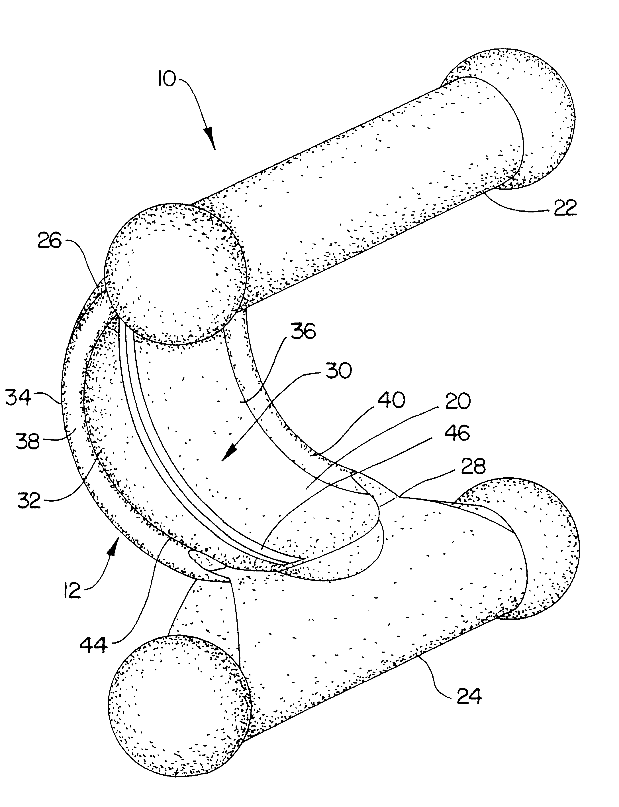
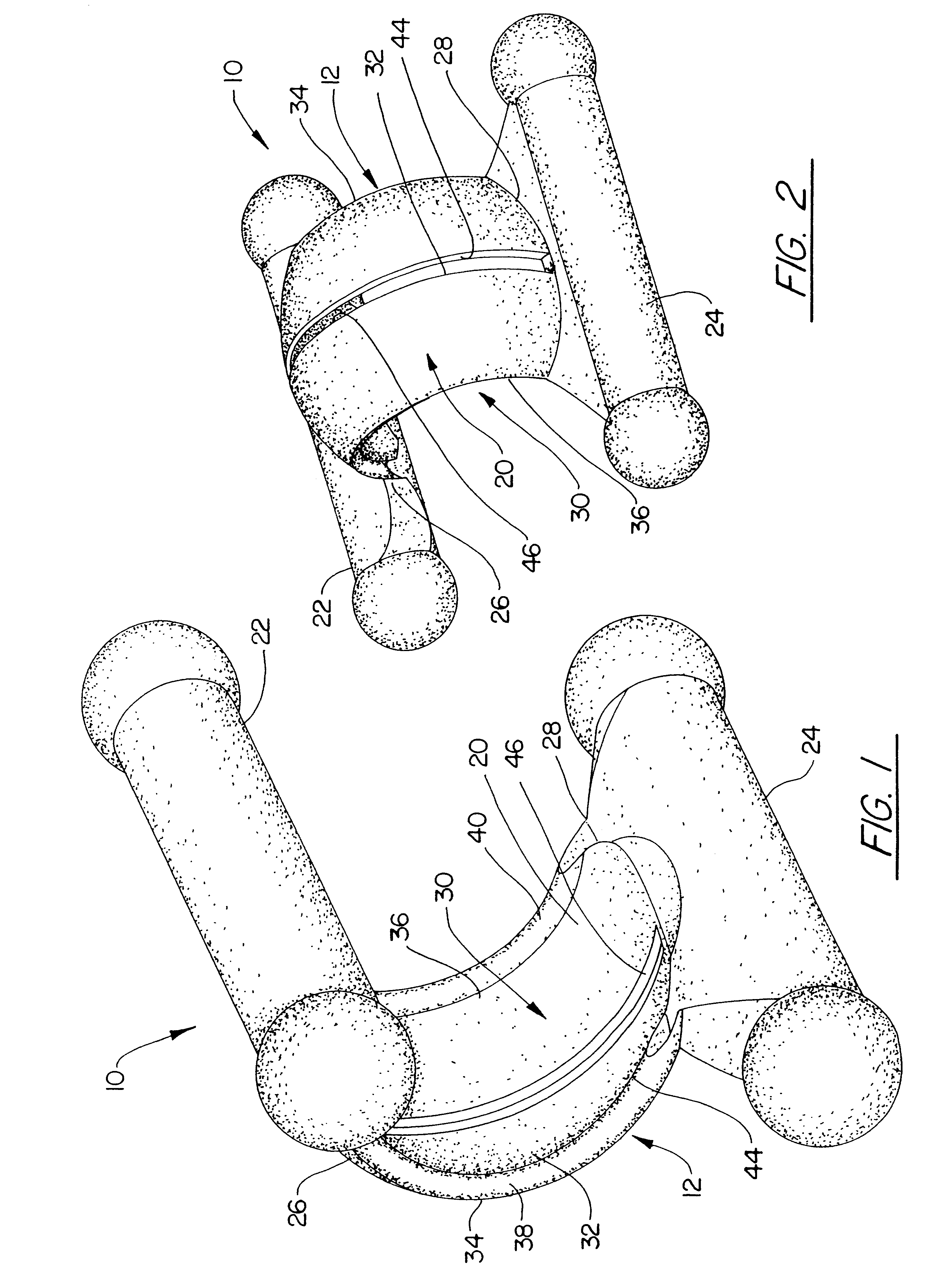
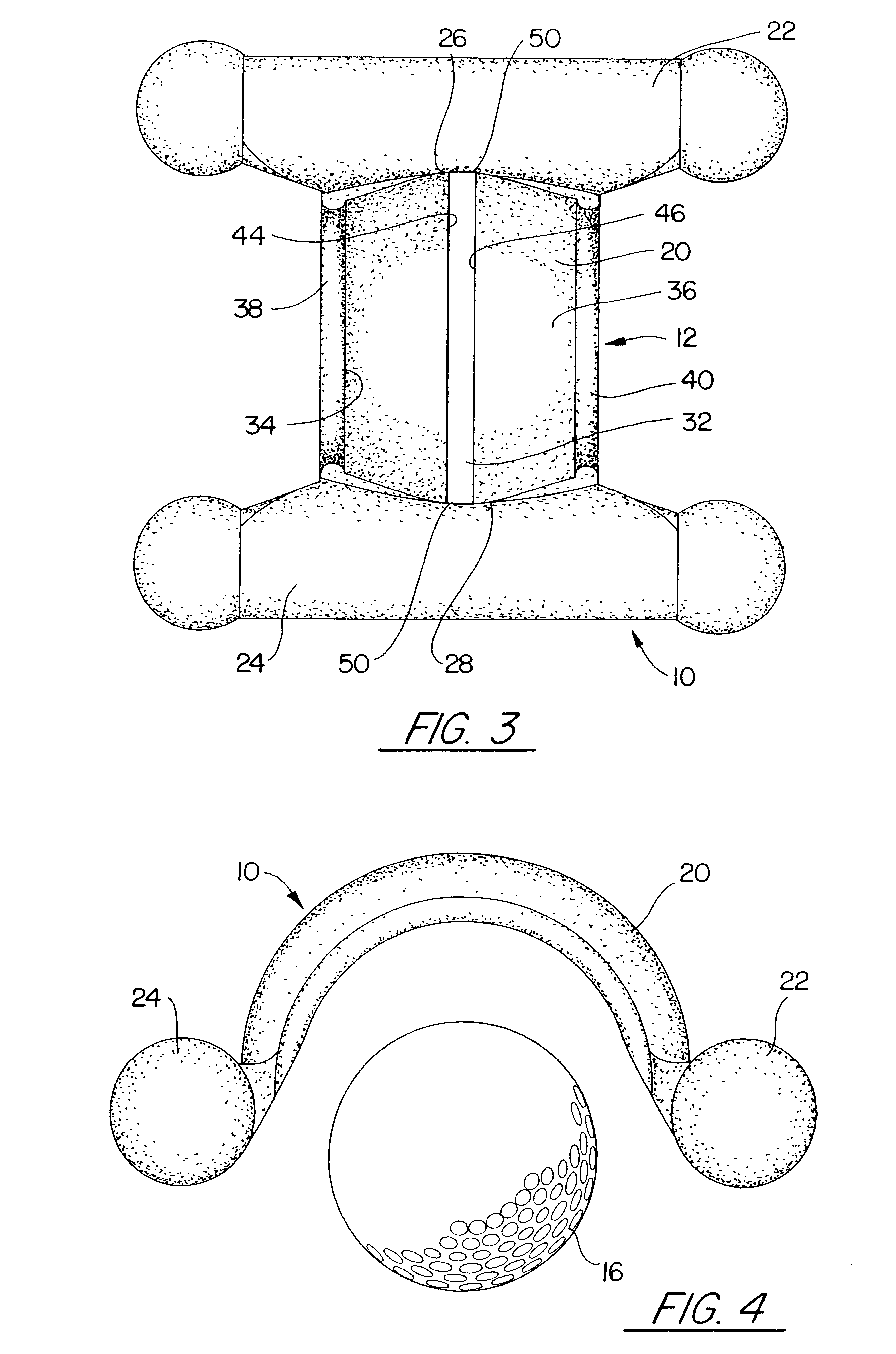
The present invention is a golf ball marking device that helps individuals mark diagnostic indicia on the surface of golf balls. The device includes a template member sized and shaped to positively engage a golf ball to be marked. The template member is characterized by a curved main body having articulation handles extending from opposite ends thereof. The template main body resembles an arched channel and forms a retention cavity into which a golf ball may be securely inserted.
An additional objective of the present invention is to provide a golf ball marking device that is lightweight and easily attached to a golf bag for remote use or to an anchoring member for securement.

Problems solved by technology

Although the '716 device may help some golfers, the wide array of components makes the '716 subject to user error and a degradation of accuracy produced by wear and tear over time.
Although the '511 device may help identify the centerplane of a selected ball, the '511 may be difficult to use in some instances.
As a result, the '511 device may be difficult to use if power is not available to operate the spinning motor.
Additionally, the '511 device may not be suitable for use with hollow "training" balls, the light weight of which will not produce sufficient friction between ball and rotor dish for proper operation.
Although known ball marking devices may help some golfers become more consistent, these devices are unsuitable in many situations.

Method used


Image

  • Golf ball marking device
  • Golf ball marking device
  • Golf ball marking device

Examples


Embodiment Construction

It is to be understood that while a certain form of the invention is illustrated, it is not to be limited to the specific form or arrangement of parts herein described and shown. It will be apparent to those skilled in the art that various changes may be made without departing from the scope of the invention and the invention is not to be considered limited to what is shown in the drawings and described in the specification.

Now with reference to FIGS. 1, 4 and 5, the ball marking assistance device 10 of the present invention is shown. By way of overview, the device 10 includes a template member 12 that cooperates with a marking device 14 to facilitate selective placement of diagnostic indicia 15 on a golf ball 16. The device 10 may also include a marking device holder 18 that allows convenient storage of the marking device 14 when not in use. The device 10 will now be described in detail.

With continued reference to FIG. 1, the template member 12 includes an arc-shaped main body 20 s...


PUM


Abstract

A golf ball marking assistance device includes a template member sized and shaped to positively engage a golf ball to be marked. The template member includes a main body that forms a resiliently-deformable retention cavity that frictionally secures a golf ball inserted therein. Articulation handles extending from opposite ends of the main body allow the template to be moved between a securing orientation and a release orientation. A marking slot extending through the main body allows use of a marking device to place diagnostic indicia, such as a stripe or stripes, onto the exterior of a golf ball secured within the retention cavity. The device may include indicia-protecting recesses that prevent unwanted contact between newly-marked indicia and the interior of the retention cavity. An attachment aperture allows connection of the device to a golf bag via a tethering member, and the device may include a marking device holder to removably secure a marking device when not in use.

Description

FIELD OF THE INVENTIONThis invention is directed to golf training aids and, in particular to a device that facilitates the marking of diagnostic indicia on the exterior of a golf ball.BACKGROUND OF THE INVENTIONGolf is a game of skill in which a set of specialized clubs is used to strike a golf ball, thereby guiding the ball around a golf course. A golf course is divided into segments, called "holes," and score is kept regarding the number of club strokes required to complete each hole. A chief goal of golf is the completion of a given course using the fewest number of strokes possible.A variety of golf equipment has been designed to improve player performance. For example, golf clubs with different lengths, weights, and club head sizes have been developed to suit the swing and stance preferences of various players. Many golfers use specialized shoes to help maintain proper footing. Some golfers even wear clothing made from fibers engineered to wick away moisture, thereby keeping th...

Claims


Application Information

Patent Timeline
IPC IPC(8): A63B45/00A63B45/02A63B69/36A63B55/00
CPCA63B45/02A63B69/3655A63B55/008A63B69/3617Y10S101/40A63B55/408
Inventor FOLEY, KEITH
Owner FOLEY KEITH
Learn More