Well screen having an internal alternate flowpath

a flow path and well screen technology, applied in the field of well screens, can solve the problems of affecting the economic life of the well, partial fracturing, and substantial voids in the gravel pack

Inactive Publication Date: 2001-04-24
SCHLUMBERGER TECH CORP +1
View PDF10 Cites 178 Cited by
  • Summary
  • Abstract
  • Description
  • Claims
  • Application Information

AI Technical Summary

Benefits of technology

As the sand pack in the perforated sector of the present screen begins to build back into the blank, alternate flowpath sector of the annulus, the high viscosity (e.g. not less than about 20 centipoises) of the carrier fluid of the slurry greatly retards further circumferential leak-off through the built-up sand pack within the annulus. The continued pumping of the slurry will now force the slurry downward through the blank, alternate flowpath sector of the annulus to a different level within the annulus where no sand pack has yet formed. The alternate flowpath sector is kept open by the slow circumferential growth of the sand pack within the annulus and by the relatively high fluid velocity in the remaining open sector of the annulus.
Once the completion interval has been fractured and / or gravel packed and the well has been put on production, the produced fluids can now flow through the newly-placed gravel pack, through the production, perforated sector of the screen and into the base pipe to be produced to the surface. By being able to deliver fracturing fluid / gravel slurry directly to different levels within the completion interval through the blank, alternate flowpath of the present screen, there will be a better distribution of gravel throughout the entire completion interval, especially when sand bridges form in the well annulus before all of the gravel has been placed. Also, since the alternate flowpath is internally formed between the two pipes, the present screen is relatively simple in construction and relatively inexpensive to build and the flowpath is protected from damage and abuse during handling and installation of the screen.

Problems solved by technology

This sand production must be controlled or it can seriously affect the economic life of the well.
A major problem in fracturing / gravel packing a well-especially where long or inclined intervals are to be completed lies in adequately distributing the fracturing fluid / gravel slurry (hereinafter referred to as "gravel slurry") over the entire completion interval.
Poor distribution of the gravel slurry throughout the interval (i.e. along the entire length of the screen) typically results in (a) only a partial fracturing of the formation and (b) a gravel pack having substantial voids therein.
Poor distribution of the gravel slurry is often caused when carrier fluid from the slurry is lost prematurely into the more permeable portions of the formation and / or into the screen, itself, thereby causing "sand bridge(s)" to form in the well annulus around the screen before the formation has been adequately fractured and all of the gravel has been placed.
While this arrangement has proven highly successful, externally-mounted shunts do have some disadvantages.
This can be very important especially when a screen is to be run into a relatively small-diameter wellbore where even fractions of an inch in its outer diameter may make the screen unusable or at least difficult to install in the well.
Another disadvantage in mounting the shunts externally lies in the fact that the shunts are exposed to damage during assembly and installation of the screen.
If the shunt is crimped or otherwise damaged during installation, it can become totally ineffective in delivering the gravel to all of the levels in the completion interval which, in turn, may result in the incomplete fracturing / packing of the interval.
However, this can make the construction of such screens more sophisticated, if not more complicated, which, in turn, normally results in substantially higher production costs.
By placing the alternate flowpath inside the screen, it is protected from damage and abuse during the handling and installation of the screen and does not increase the effective diameter of the screen.
When this occurs, a "sand bridge" will have likely already been formed in the well annulus which, in the absence of an alternate flowpath, would block further flow of slurry through the well annulus and would likely result in an unsuccessful completion.

Method used


Image

  • Well screen having an internal alternate flowpath
  • Well screen having an internal alternate flowpath
  • Well screen having an internal alternate flowpath

Examples


Embodiment Construction

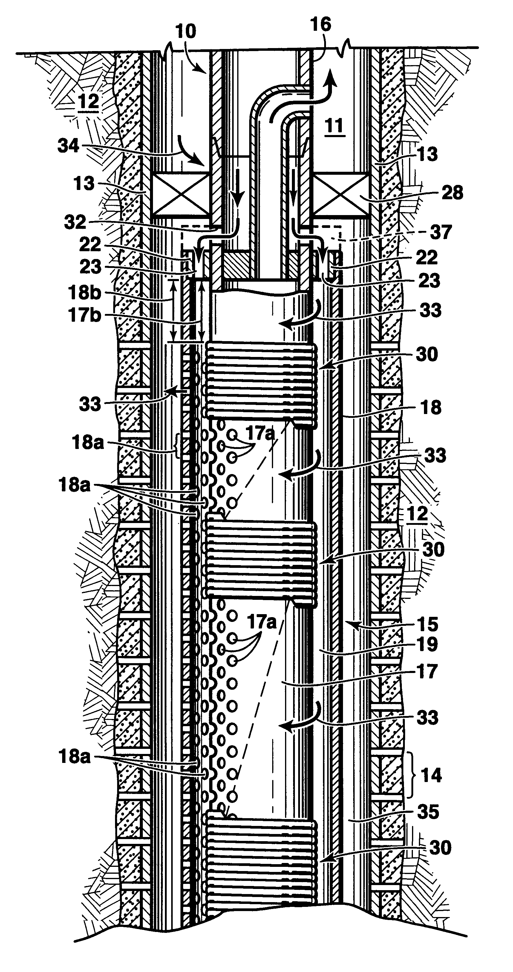
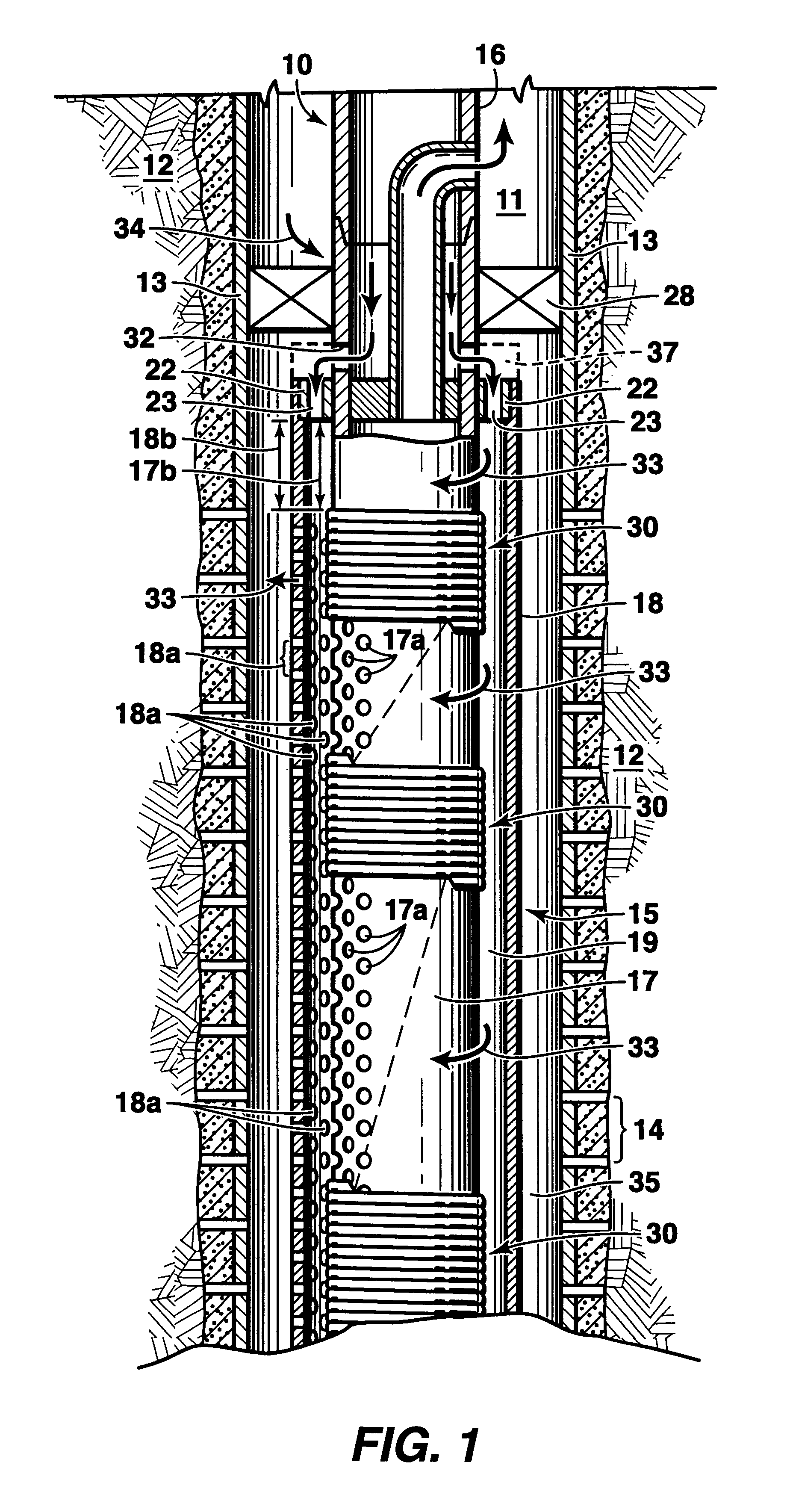
Referring more particularly to the drawings, FIG. 1 illustrates the present well tool 10 in an operable position within the lower end of a producing and / or injection wellbore 11. Wellbore 11 extends from the surface (not shown) and into or through formation 12. Wellbore 11, as shown, is cased with casing 13 having perforations 14 therethrough, as will be understood in the art. While wellbore 11 is illustrated as being a substantially vertical, cased well, it should be recognized that the present invention can be used equally as well in "open-hole" and / or underreamed completions as well as in horizontal and / or inclined wellbores. Well tool 10 (e.g. gravel pack screen) may be of a single length or it may be comprised of several joints (only the portion of the upper joint is shown) which are connected together with threaded couplings and / or blanks or the like as will be understood in the art.

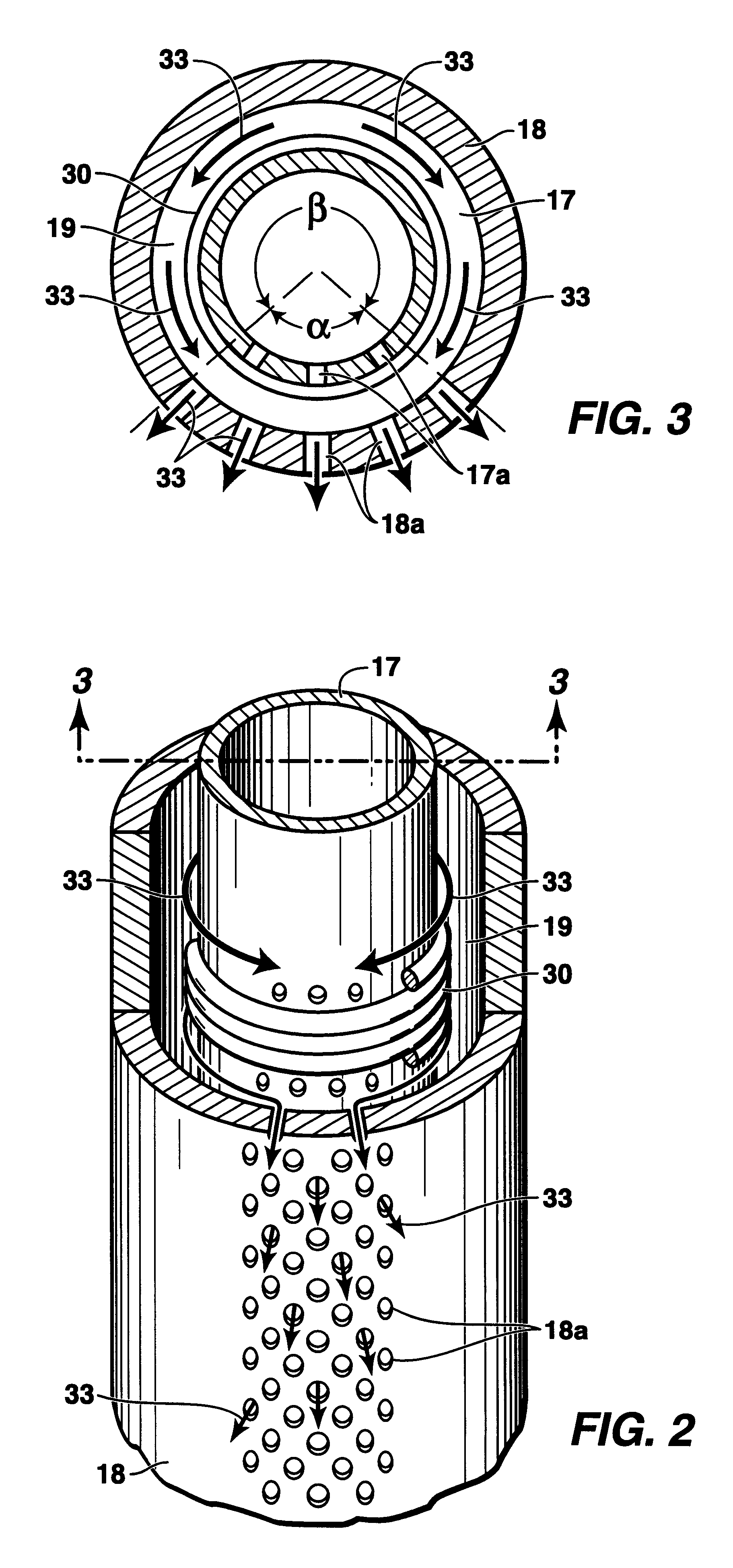
As shown, a typical joint 15 of gravel pack screen 10 is comprised of a base pipe 17 which is p...


PUM


Abstract

A well screen having an internal, blank alternate flowpath for delivering fracturing fluid / gravel slurry to different levels within a well annulus. The well screen includes an outer pipe which is positioned over a base pipe thereby forming an annulus therebetween. The circumference of each pipe has a perforated sector and a blank sector, both of which extend along their respective lengths. When assembled, the respective perforated sectors are aligned to form a perforated, production sector and the respective blank sectors are aligned to form the blank, alternate flowpath. The base pipe is wrapped with wire to prevent solids from flowing through the openings therein. Slurry is pumped into the annulus where it flows circumferently from the blank, alternate flowpath to exit into the well annulus through the openings in the perforated sector of the annulus.

Description

DESCRIPTION1. Technical FieldThe present invention relates to a well screen and in one of its aspects relates to a well screen for fracturing / gravel packing a well having an internal, alternate flowpath which, in turn, is formed between the aligned, blank sectors of two pipes.2. Background of the InventionIn producing hydrocarbons or the like from certain subterranean formations, it is common to produce large volumes of particulate material (e.g. sand) along with the formation fluids, especially when the formation has been fractured to improve flow therefrom. This sand production must be controlled or it can seriously affect the economic life of the well. One of the most commonly-used techniques for controlling sand production is known as "gravel packing". In a typical gravel pack completion, a screen is positioned within the wellbore adjacent the interval to be completed and a gravel slurry is pumped down the well and into the well annulus around the screen. As liquid is lost from ...

Claims


Application Information

Patent Timeline
Patent Type & Authority Patents(United States)
IPC IPC(8): E21B43/08E21B43/02E21B43/04
CPCE21B43/04E21B43/08
Inventor JONES, LLOYD G.TIBBLES, RAYMOND J.HURST, GARY D.
Owner SCHLUMBERGER TECH CORP
Why Eureka
Try Eureka