
Antenna device

Inactive Publication Date: 2001-04-24
MURATA MFG CO LTD
View PDF5 Cites 62 Cited by
  • Summary
  • Abstract
  • Description
  • Claims
  • Application Information

AI Technical Summary

Benefits of technology

The antenna unit in accordance with an embodiment of the present invention has a wavelength shortening effect because the base member is formed of either a material having a dielectric constant .epsilon. of 1<.epsilon.<130 or a material having a relative permeability .mu. of 1<.mu.<7.

Problems solved by technology

Thus, such an antenna cannot be readily used for mobile communication or the like which requires a compact antenna.
In these cases there is a problem that the antenna gain is decreased because of the effect of the dielectric substance.

Method used


Image

  • Antenna device
  • Antenna device
  • Antenna device

Examples


Embodiment Construction

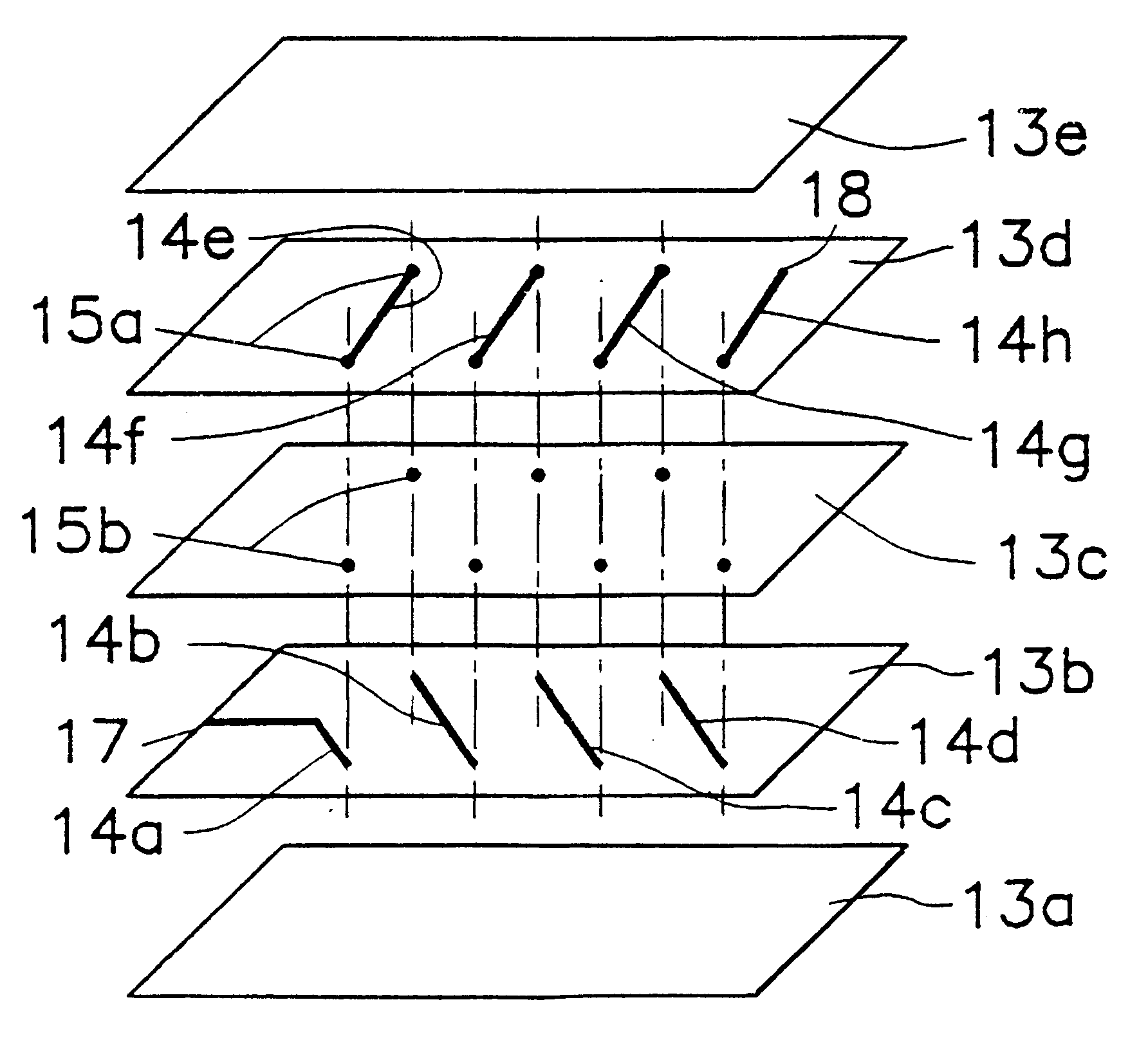
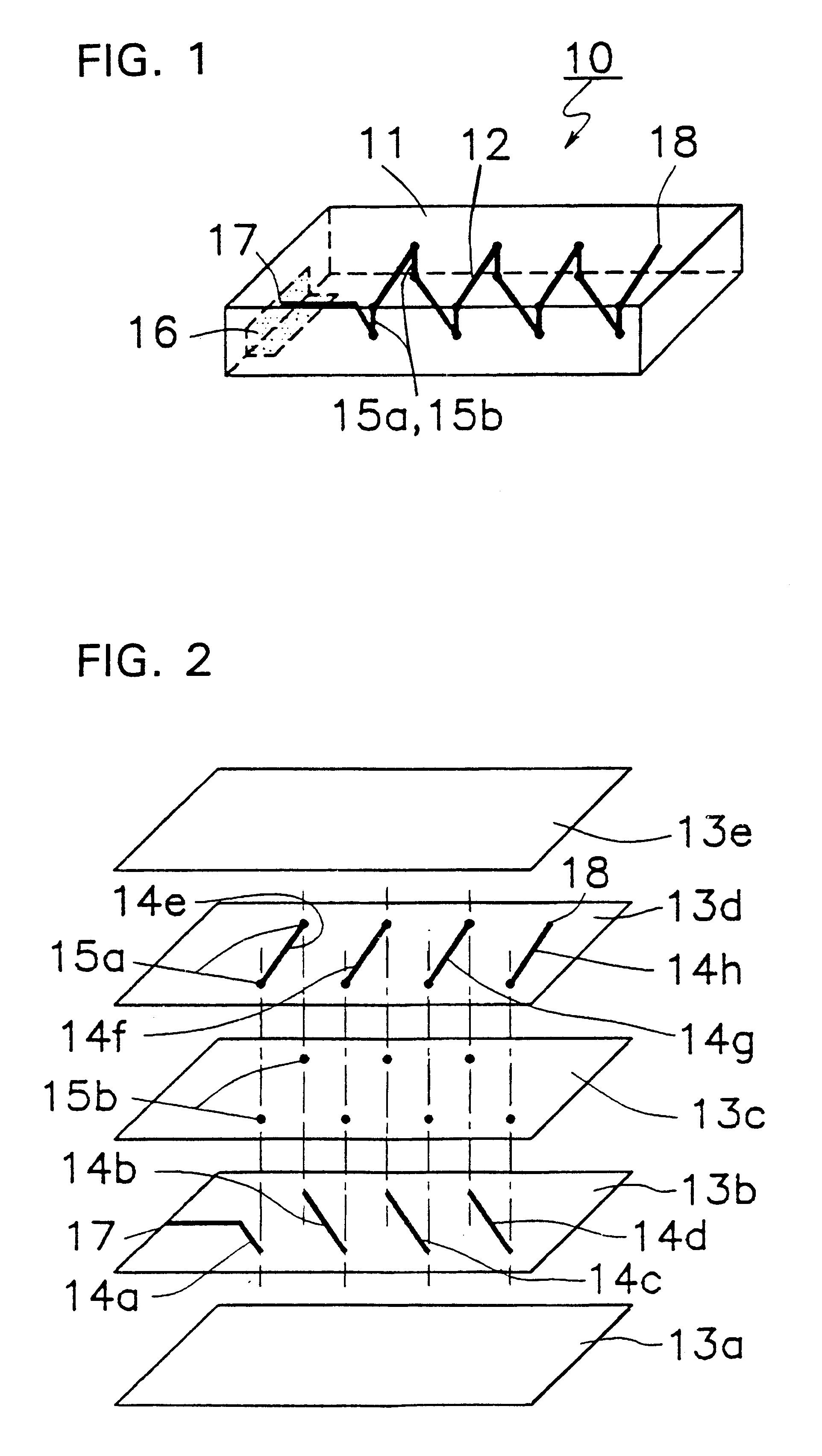
FIGS. 1 and 2 are an isometric view and an exploded isometric view illustrating an embodiment of a chip antenna 10 in accordance with the present invention.

The chip antenna 10 comprises a conductor 12 which is spiraled along the longitudinal direction in a rectangular dielectric base member 11. The dielectric base member is formed by laminating rectangular sheets 13a-13e, each having a dielectric constant of 2 to 130, or having a relative permeability of 2 to 7, as shown in Tables 1 and 2.

TABLE 2

In Tables 1 and 2, the sample having a dielectric constant of 1 and a relative permeability of 1 is not selected because the sample is electrically identical to the prior art antenna.

The Q.multidot.f in Table 1 represents the product of the Q value and a measuring frequency and is a function of the material. The threshold frequency in Table 2 represents the frequency that the Q value is reduced by half to an almost constant Q value at a low frequency region, and represents the upper limit of...


PUM


Abstract

An antenna device, comprising an antenna unit including basic body comprising at least one of dielectric ceramic and magnetic ceramic, at least one conductor disposed at least one of inside and on a surface of the basic body, and a feeding electrode for applying a voltage to the conductor disposed on the surface of the basic body; a mounting board on which the antenna unit is mounted; a ground part in association with the mounting board and adapted to resonate with the antenna unit; and a length in the polarization direction of a radio wave of the ground part being about lambd / 4 or more, where lambd is a wavelength of the radio wave, the basic body comprising a first generally planar sheet having a plurality of spaced, first conductors formed on one major surface thereof and a second generally planar sheet having a plurality of spaced second conductors formed on one major surface thereof; the first and second generally planar sheets being laminated together to form an elongated structure wherein respective pairs of the first and second conductors are coupled to one another to form respective spiral loops of a spiral antenna so that a central axis of the spiral antenna extends generally parallel to a longitudinal direction of the elongated structure; each of the sheets being formed of a material having a permeability of 1<mu<7 or a dielectric constant epsi of 1<epsi<130; and a feeding terminal coupled to one end of the spiral antenna so that the antenna unit forms a mono-pole antenna, the antenna unit and the ground part together functioning as a dipole antenna.

Description

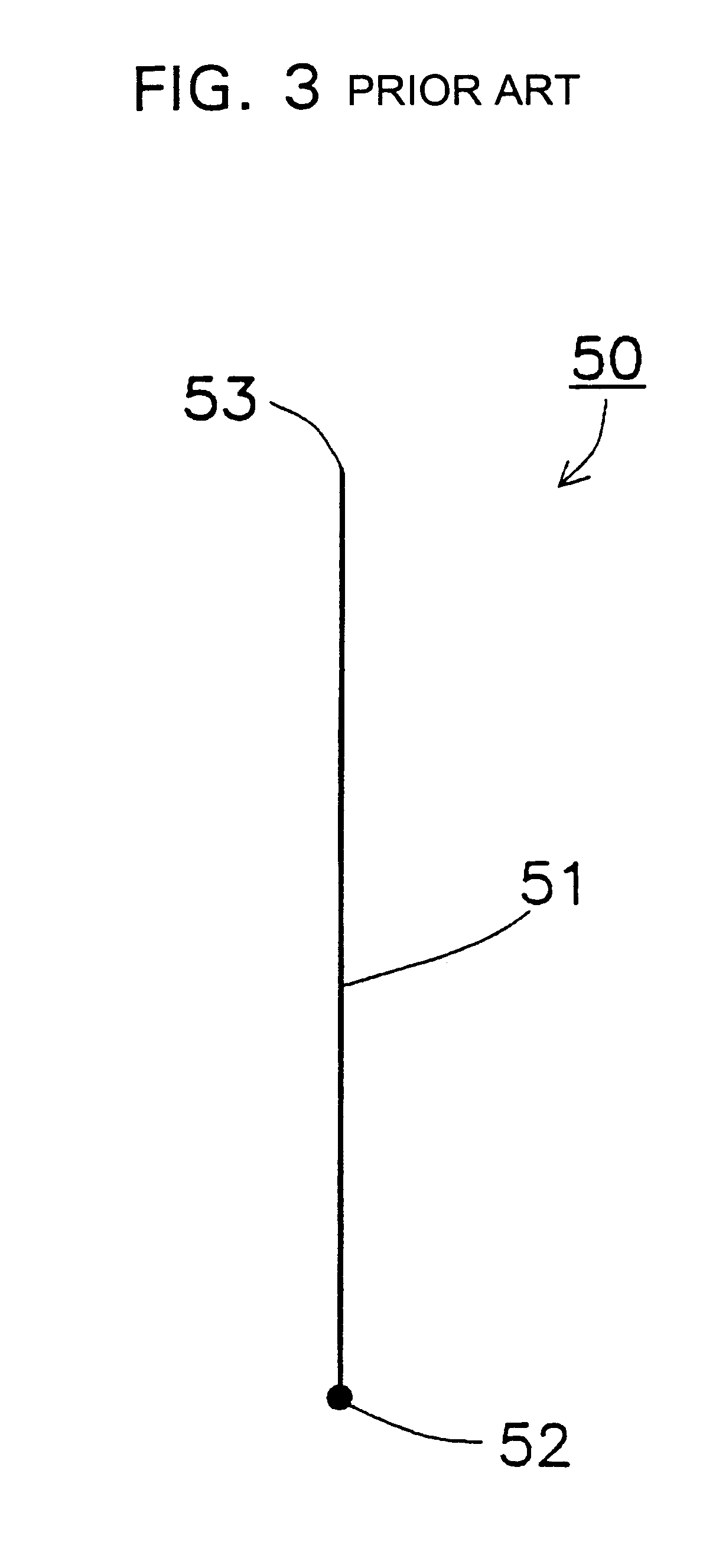
1. Field of the InventionThe present invention relates to antenna devices and chip antennas. In particular, the present invention relates to an antenna device used for mobile communication, cellular communication, local area networks (LAN), television, radio, etc. Further, the present invention makes use of a chip antenna of small size, itself a monopole antenna, which, together with a ground part, functions like a dipole antenna, even though it is of small size.2. Description of the Related ArtFIG. 3 shows a prior art monopole antenna 50. The monopole antenna 50 has a conductor 51, one end 52 of the conductor 51 being a feeding point and the other end 53 being a free end in the air (dielectric constant .epsilon.=1 and relative permeability .mu.=1).Because the conductor of the antenna is present in the air in linear antennas, such as the prior monopole antenna 50, the size of the antenna conductor becomes larger. For example, when the wavelength in the vacuum is .lambda..sub.0 in th...

Claims


Application Information

Patent Timeline
IPC IPC(8): H01Q9/28H01Q1/36H01Q9/04H01Q1/38
CPCH01Q1/362H01Q1/38H01Q9/285
Inventor TSURU, TERUHISAMANDAI, HARUFUMISHIROKI, KOJIASAKURA, KENJIKANBA, SEIJI
Owner MURATA MFG CO LTD
Learn More