
Trolling motor mount stabilizer

a stabilizer and motor technology, applied in the direction of propulsive elements, marine propulsion, vessel construction, etc., can solve the problems of high shock load, high risk of motor damage, and non-traditional use of trolling motors as primary sources of propulsion

Inactive Publication Date: 2001-05-01
BRP US
View PDF16 Cites 12 Cited by
  • Summary
  • Abstract
  • Description
  • Claims
  • Application Information

AI Technical Summary

Benefits of technology

In accordance with another aspect of the invention, a trolling motor mount stabilizing kit is provided for installation on a motor bracket of an existing and previously assembled motor mount assembly. The kit includes a substantially planar member adapted to be rigidly and directly mounted to a surface of the motor bracket. The support is to be mounted such that the planar member extends a distance from the motor bracket and substantially parallel with the mounting surface. Fasteners are provided for rigidly mounting the planar member to the motor bracket. A soft resilient member adapted to be affixed to the distal end of the planar support member is also provided for cushioning or absorbing shock of the mount assembly. After implementation of the kit, the planar member serves to sustain an overhung load of the trolling motor while in a stowed position.

Problems solved by technology

However, trolling motors are not typically used as the primary source of propulsion on a boat.
Likewise, when the boat is being towed on a trailer, the trolling motor may be placed in a stowed position to keep the motor from projecting outward of the boat and thus causing a hazard during transit and potentially damaging the motor.
If the motor were allowed to rest directly on the deck, the motor would be highly susceptible to shock loads during transit, either across a body of water, or in tow.
Shock loads have been known to cause significant damage to the trolling motors as well as to the mounting brackets and associated hardware.
Such a design, while reducing direct shock load, may still allow bouncing due to the cantilever created beyond the location of the stop.
Another result of placing the stop at such a location is that the cantilever produced by the overhung load of the motor places a large moment on the stop.
This moment creates significant stress, fatigue and wear on the stop and associated components.
Ultimately, such conditions may cause the stop to fail prematurely.
While such a design changes the moment and load experienced by the link, it also requires disassembly of the pivoting connection at the motor bracket.
Such a design does not necessarily assure a rigid and stable support since it is integrated with a pivotal connection.
Thus, not all brackets and mounting assemblies may be able to accommodate such support without greater additional, and possibly significant alterations and modifications to existing structures and components.

Method used


Image

  • Trolling motor mount stabilizer
  • Trolling motor mount stabilizer
  • Trolling motor mount stabilizer

Examples


Embodiment Construction

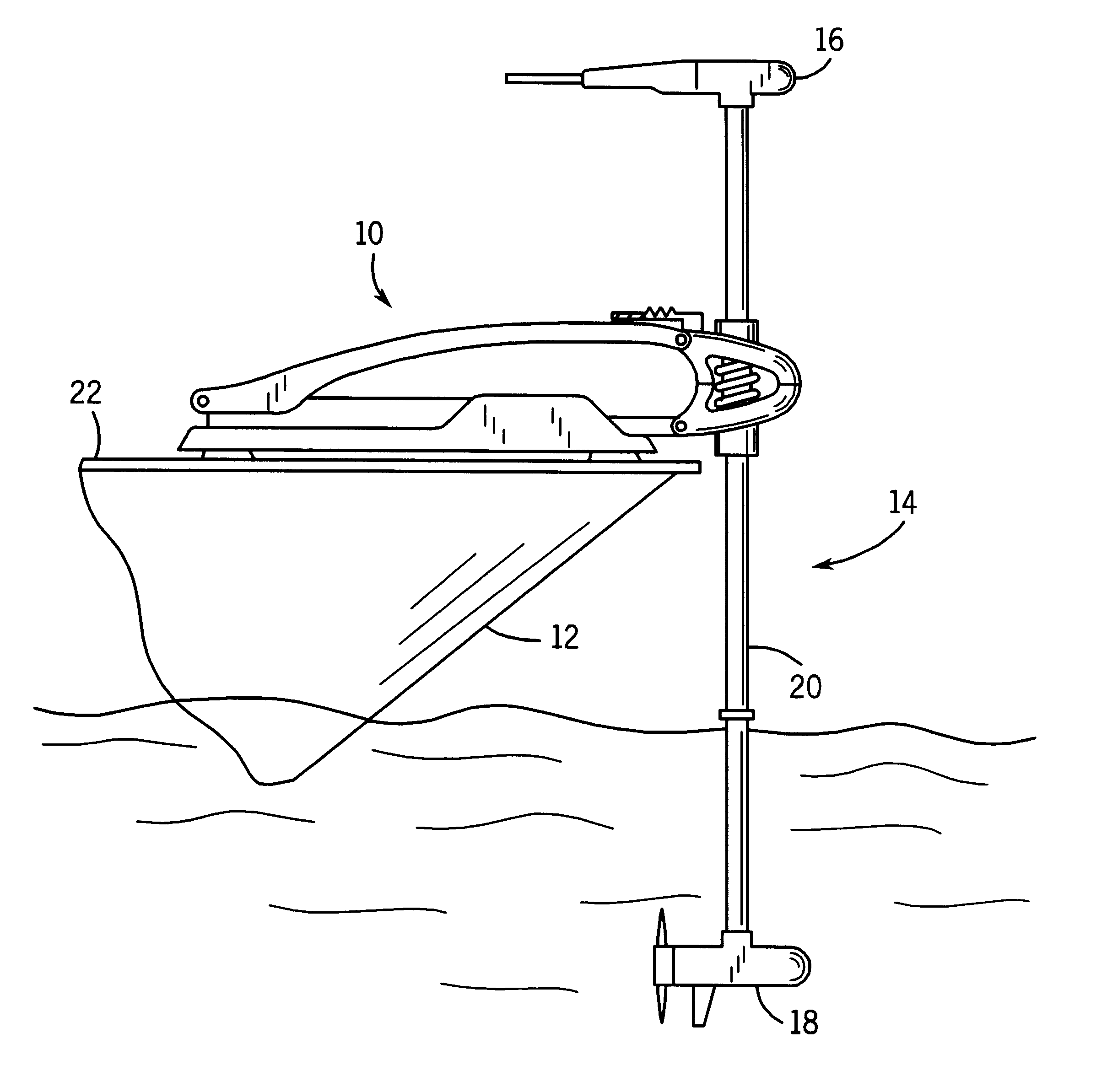
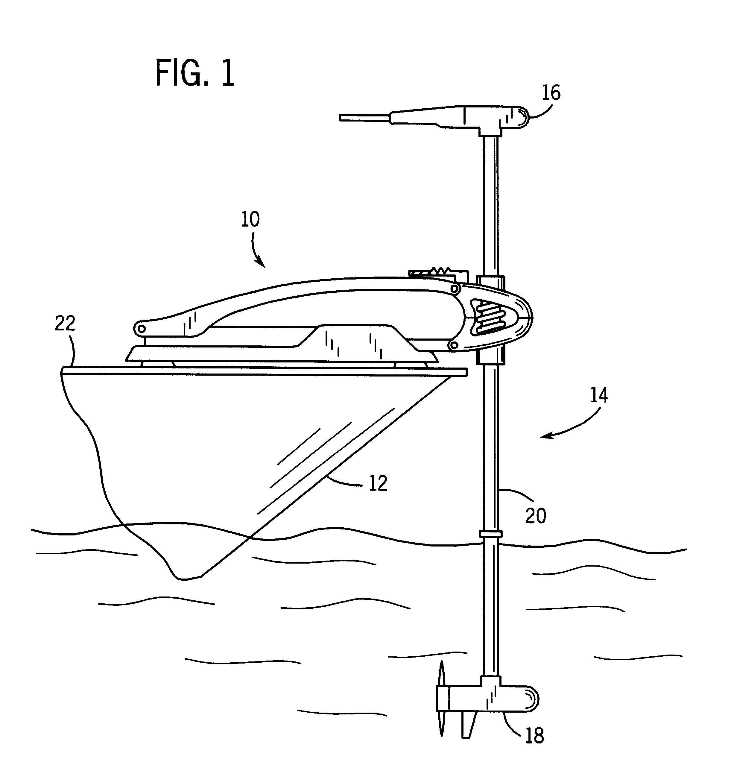
Turning now to the drawings and referring first to FIG. 1, a mount assembly 10 on a boat 12 is adapted for a supporting a trolling motor 14. The trolling motor 14 is generally of a type known to those skilled in the art, and includes head section 16 and a prop section 18. Connecting the two sections is a substantially rigid tubular shaft member 20. The mount assembly 10 is affixed to the gunwale or deck 22 of the boat. FIG. 1 shows the mount assembly 10 and trolling motor 10 in an operable position, wherein the prop section 18 of the trolling motor 14 operates to quietly propel the boat 12 through a body of water. As described below, the mount assembly 10 is also used to stow the trolling motor 14 on the deck 22 of the boat when it is not in use.

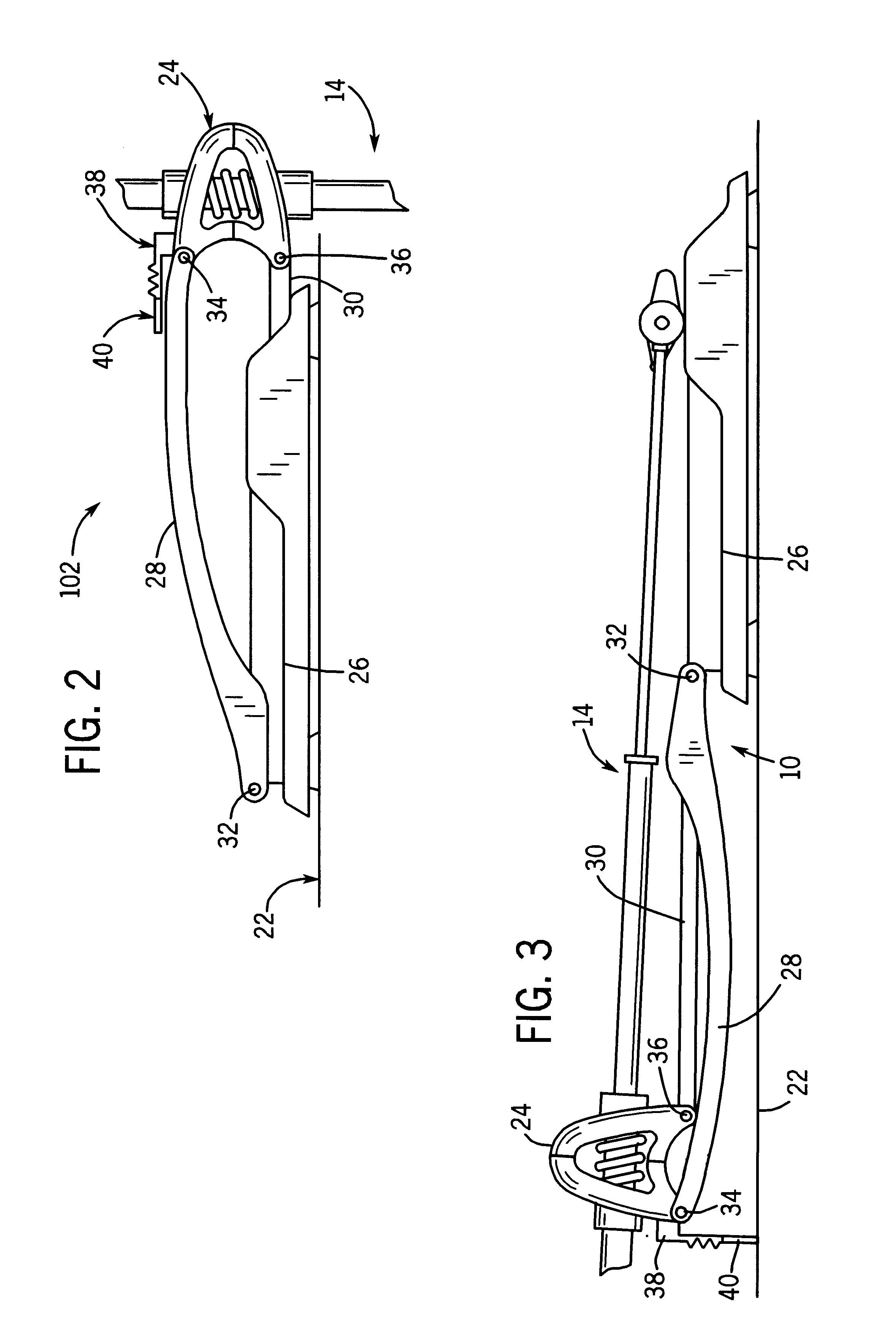
Turning now to FIGS. 2 and 3, an enlarged view of the mount assembly 10 is shown, with FIG. 2 depicting the trolling motor in the operable position, while FIG. 3 depicts the mount assembly 10 when the trolling motor 14 is in the stowed posit...


PUM


Abstract

A mount assembly for a trolling motor is provided. The mount assembly includes a bracket adapted to support the trolling motor. A pivoting member, such as a link or an arm, has a first end pivotally coupled to the bracket. The pivoting member is also pivotally coupled to an abutment adjacent a boat deck or gunwale at its second end. A support member is rigidly affixed to a surface of the bracket such that the support member sustains the overhung load of the trolling motor while it is in the stowed position on the boat deck or gunwale. The support member is flat and unobtrusive when the motor is in its run position.

Description

1. Field Of The InventionThe present invention relates generally to trolling motors. More specifically the present invention relates to a stabilizer used in conjunction with a trolling motor mount to minimize movement of the trolling motor when not in use.2. Description Of The Related ArtTrolling motors are typically light weight electric propulsion units used to propel fishing boats. Because of the small size and quiet operation of such motors, they are often used to propel the boat into remote and shallow regions of a body of water. The motors may be operated and controlled without diverting the user from fishing in many instances. However, trolling motors are not typically used as the primary source of propulsion on a boat. Rather, when it is desirous to travel significant distances in the boat, the trolling motor is typically placed in stowed position on the deck or gunwale of the boat while the primary motor propels the boat. Likewise, when the boat is being towed on a trailer,...

Claims


Application Information

Patent Timeline
IPC IPC(8): B63H21/00B63H21/30B63H20/00
CPCB63H20/007B63H21/30
Inventor GRIFFITH, SR., THOMAS E.TYLER, CALVIN
Owner BRP US
Learn More