

Trolling motor device
a motor device and troll technology, applied in the direction of propulsive elements, marine propulsion, vessel construction, etc., can solve the problems of significant force required to lift the drive unit using the pull cord in and out of the boat, interfere with the user's fishing, and the length of the drive unit and the mounting unit occupies the deck space, so as to reduce the overall size and ease of operation , the effect of less for
- Summary
- Abstract
- Description
- Claims
- Application Information
AI Technical Summary
Benefits of technology
Problems solved by technology
Method used
Image

Examples
Embodiment Construction
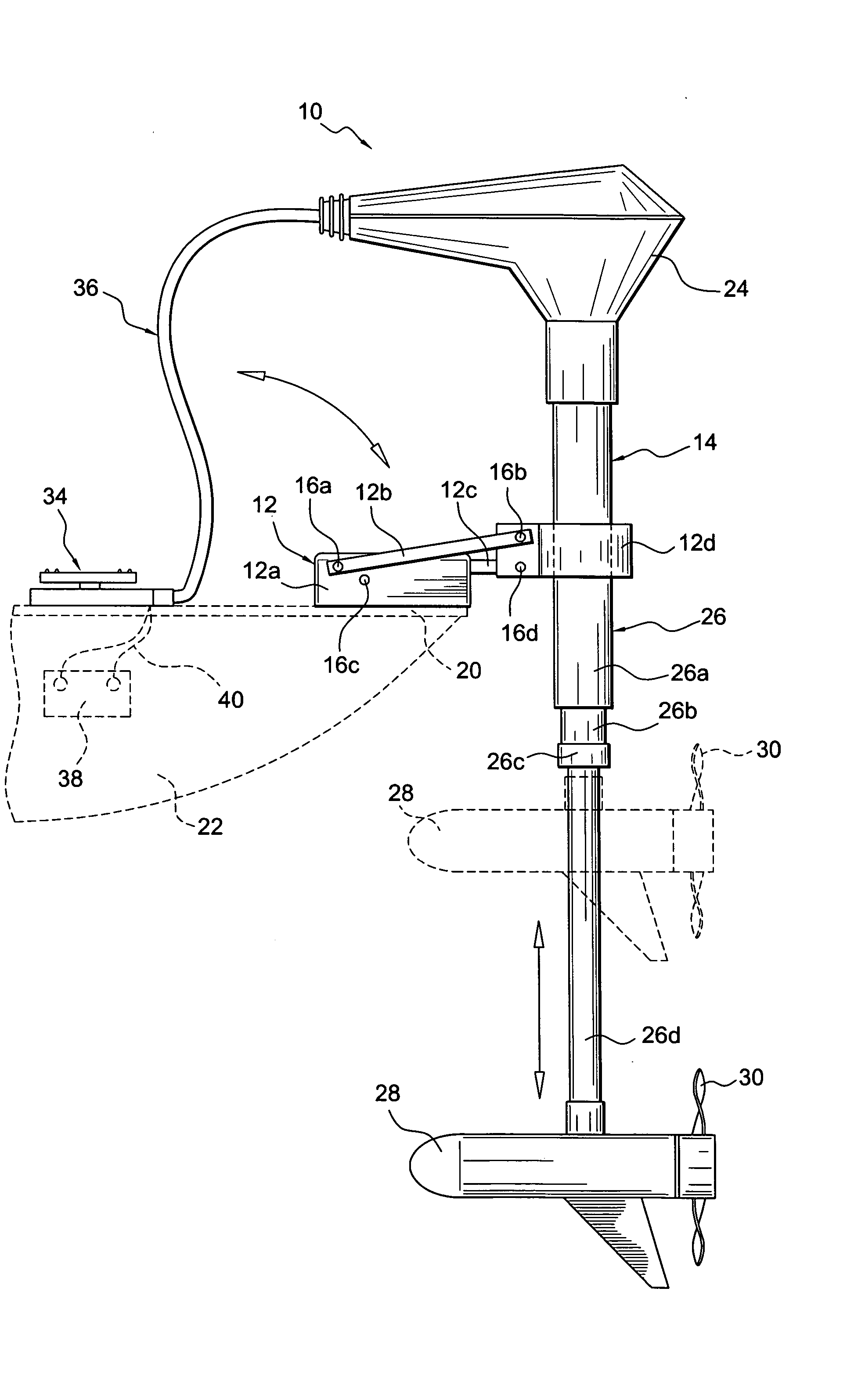
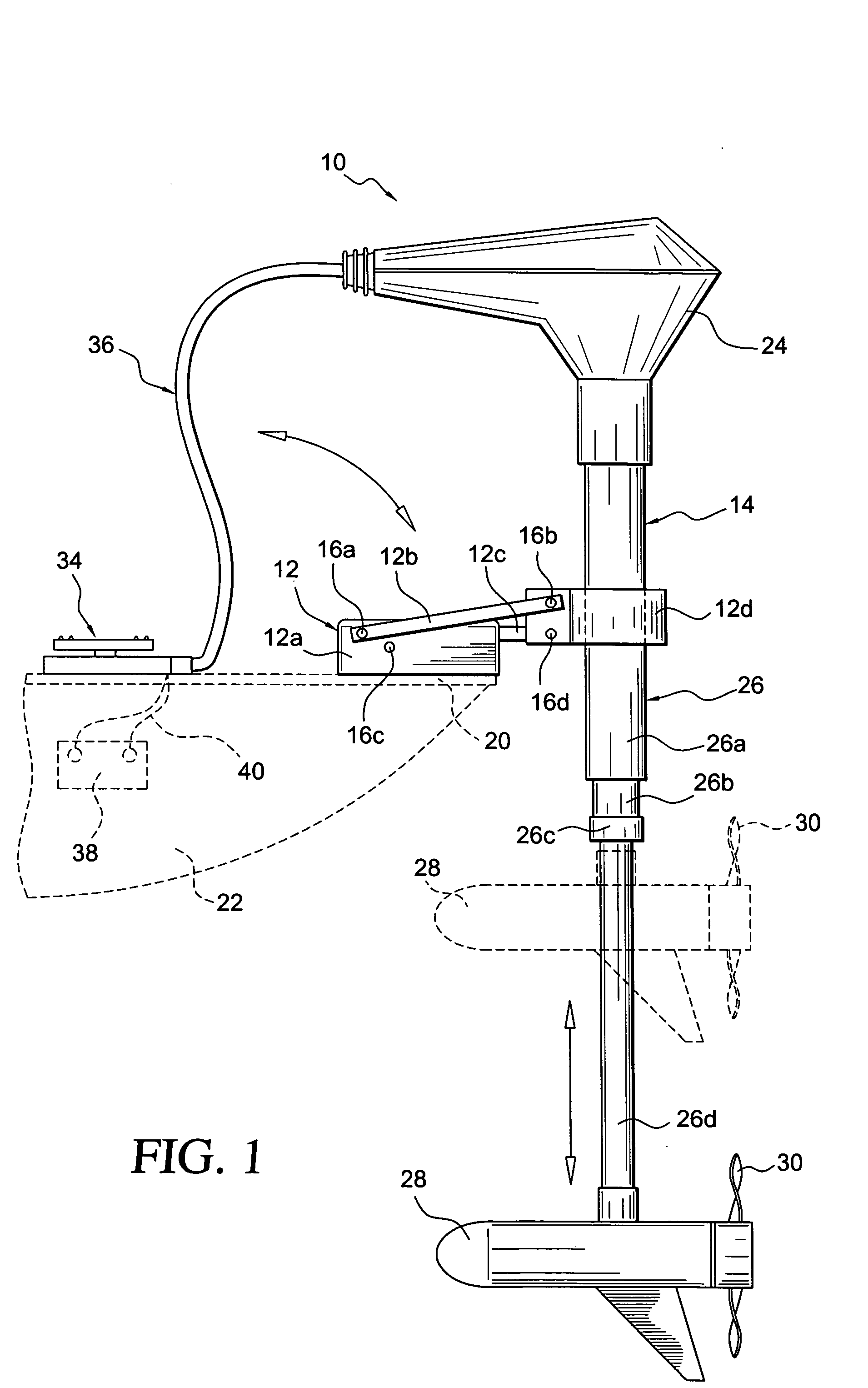
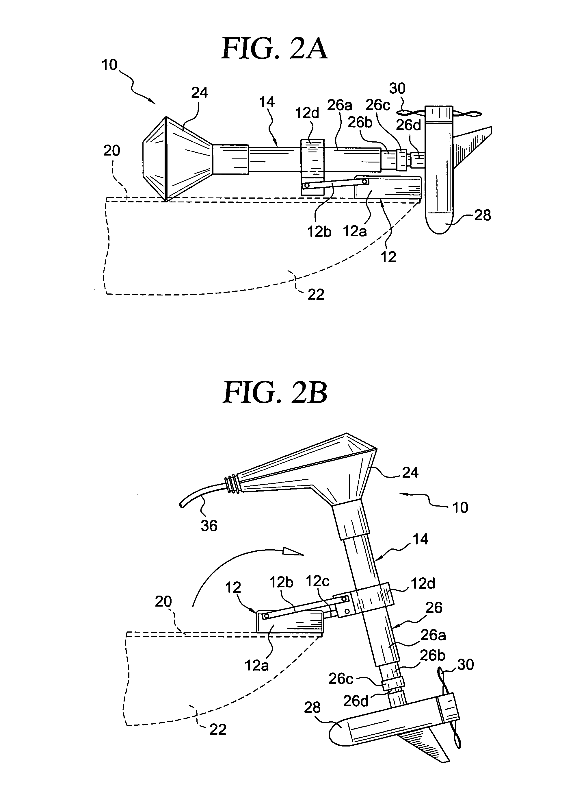
[0097] A preferred embodiment of the trolling motor device 10 according to the present invention is shown in FIGS. 1-4.
[0098] The trolling motor device 10 includes a mounting unit 12 connected to a drive unit 14 by a pivotable connection 16. The mounting unit 12 includes a mounting plate 12a having a pair of inwardly extending flanges 12b to be secured by fasteners 18 (e.g. stainless or brass screws) to an upper surface of the deck 20 of the boat 22.
[0099] The drive unit 14 includes an upper steering unit 24 connected to an upper end of drive unit housing 26, and a lower drive unit 28 connected to a lower end of the drive unit housing 26. The upper steering unit 24 includes a rack and pinion arrangement for mechanically rotating the drive unit housing 26b, 26d for steering the boat 22. The lower drive unit 28 is fitted with a propeller 30, and includes an electric drive motor (e.g. 12 volt, 24 volt, 36 volt DC electric motor) for rotating or driving the propeller 30.
[0100] The tr...
PUM
 Abstract
Description
Claims
Application Information