Constant velocity joint and method of making an outer race therefor

a constant velocity joint and outer race technology, applied in the field of constant velocity joints, can solve the problems of reducing yield, difficult to achieve an increase in precision, and inability to easily increase the precision of track grooves

Inactive Publication Date: 2001-05-01
NTN CORP
View PDF7 Cites 29 Cited by
  • Summary
  • Abstract
  • Description
  • Claims
  • Application Information

AI Technical Summary

Problems solved by technology

In making the outer race for this type of the constant velocity joint, the use of the working process in which a milling or grinding technique is used, tends to take a relatively long time to make, renders it to be difficult to achieve an increase in preciseness and tends to reduce the yield.
However, in the case where the track grooves are formed by the use of the milling process as described under item (1) above, difficulty has been encountered in that the precision of the track grooves cannot easily be incr

Method used


Image

  • Constant velocity joint and method of making an outer race therefor
  • Constant velocity joint and method of making an outer race therefor
  • Constant velocity joint and method of making an outer race therefor

Examples


Embodiment Construction

The preferred embodiment of the present invention will now be described with reference to FIGS. 1 to 17.

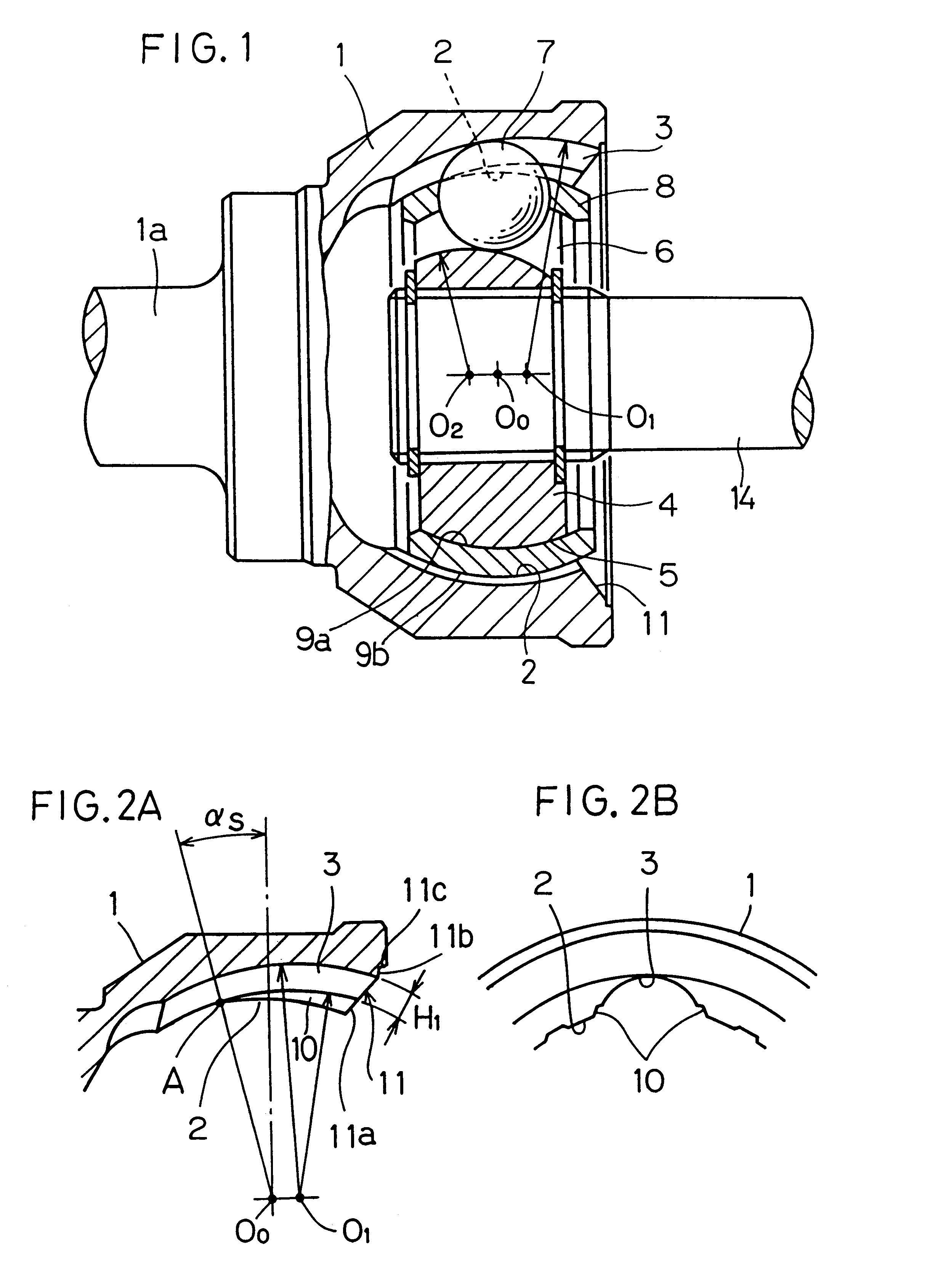
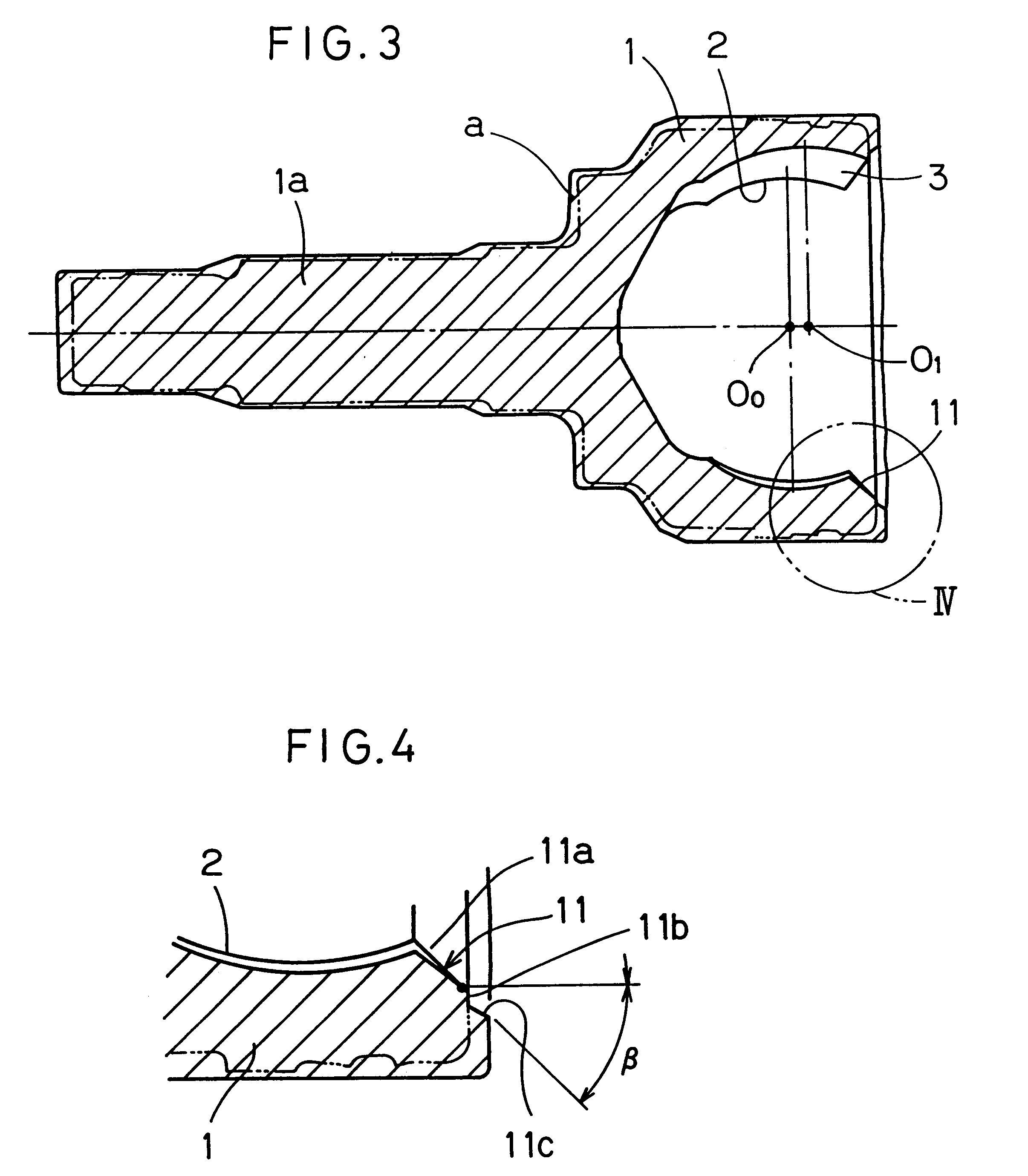
FIG. 1 illustrates a constant velocity joint. This constant velocity joint includes an outer race 1 having a spherical inner surface 2 formed with a plurality of track grooves 3 so as to extend in a direction parallel to an axial direction thereof, an inner race 4 having a spherical outer surface 5 formed with track grooves 6 equal in number to the number of the track grooves 3 in the outer race 1 and extending in an axial direction of the inner race 4; and torque transmitting balls 7 rollingly retained by a cage 8, that is positioned between the outer and inner races 1 and 4, and received in part within the associated track grooves 2 in the outer race 1 and in part within the associated track grooves 6 in the inner race 4. The cage 8 intervening between the outer and inner races 1 and 4 has spherical inner and outer surfaces 9a and 9b opposite to each other and is positioned with...


PUM

PropertyMeasurementUnit
Velocityaaaaaaaaaa
Torqueaaaaaaaaaa

Abstract

A constant velocity joint includes an outer race (1) having a spherical inner surface (2) with track grooves (3) each extending in an axial direction thereof, an inner race having a spherical outer surface (5) formed with track grooves (6) equal in number to the number of the track grooves (3) in the outer race (1), a plurality of torque transmitting balls (7) sandwiched between the inner race (4) and the outer race (1) and accommodated in part in the track grooves (6) in the inner race (4) and in part in the track grooves (3) in the outer race (1), and a cage (8) for retaining the torque transmitting balls (7) while being guided by and between the spherical inner surface (2) of the outer race (1) and the spherical outer surface (5) of the inner race (4). This constant velocity joint of the structure described above is featured in that at least the track grooves (3) in the outer race (1) and an entry chamfer (11) of the outer race (1) are formed by a plastic working process. A method of making the outer race (1) in the constant velocity joint is also provided.

Description

1. Field of the InventionThe present invention relates to a constant velocity joint which may be mainly used in association with an automobile shaft, and also to a method of making an outer race used in the constant velocity joint.2. Description of the Prior ArtA constant velocity joint has been well known in the art which comprises an outer race having a spherical inner surface formed with track grooves, an inner race having a spherical outer surface formed with track grooves, a plurality of torque transmitting balls sandwiched accommodated in between the inner race and the outer race, and a cage for retaining the torque transmitting balls. The outer race has an open edge formed with an entry chamfer to provide an outwardly flaring surface so that at the time of inclination of one of the inner and outer races relative to the other, a shaft mounted with the inner race will not collide against the open edge of the outer edge.In making the outer race for this type of the constant velo...

Claims


Application Information

Patent Timeline
IPC IPC(8): B21K1/76B21K1/00F16D3/16F16D3/224B21D22/26F16D3/20
CPCB21K1/762B21K1/765F16D3/2245F16D2250/00F16D2003/22309F16D2250/0023
Inventor IIHARA, MICHIOTAKAHARA, YASUSHIYAMAGUCHI, MASAMI
Owner NTN CORP
Why Eureka
Try Eureka