
Apparatus for vacuum impulse forming of heated glass sheets

Inactive Publication Date: 2001-05-08
GLASSTECH
View PDF12 Cites 36 Cited by
  • Summary
  • Abstract
  • Description
  • Claims
  • Application Information

AI Technical Summary

Benefits of technology

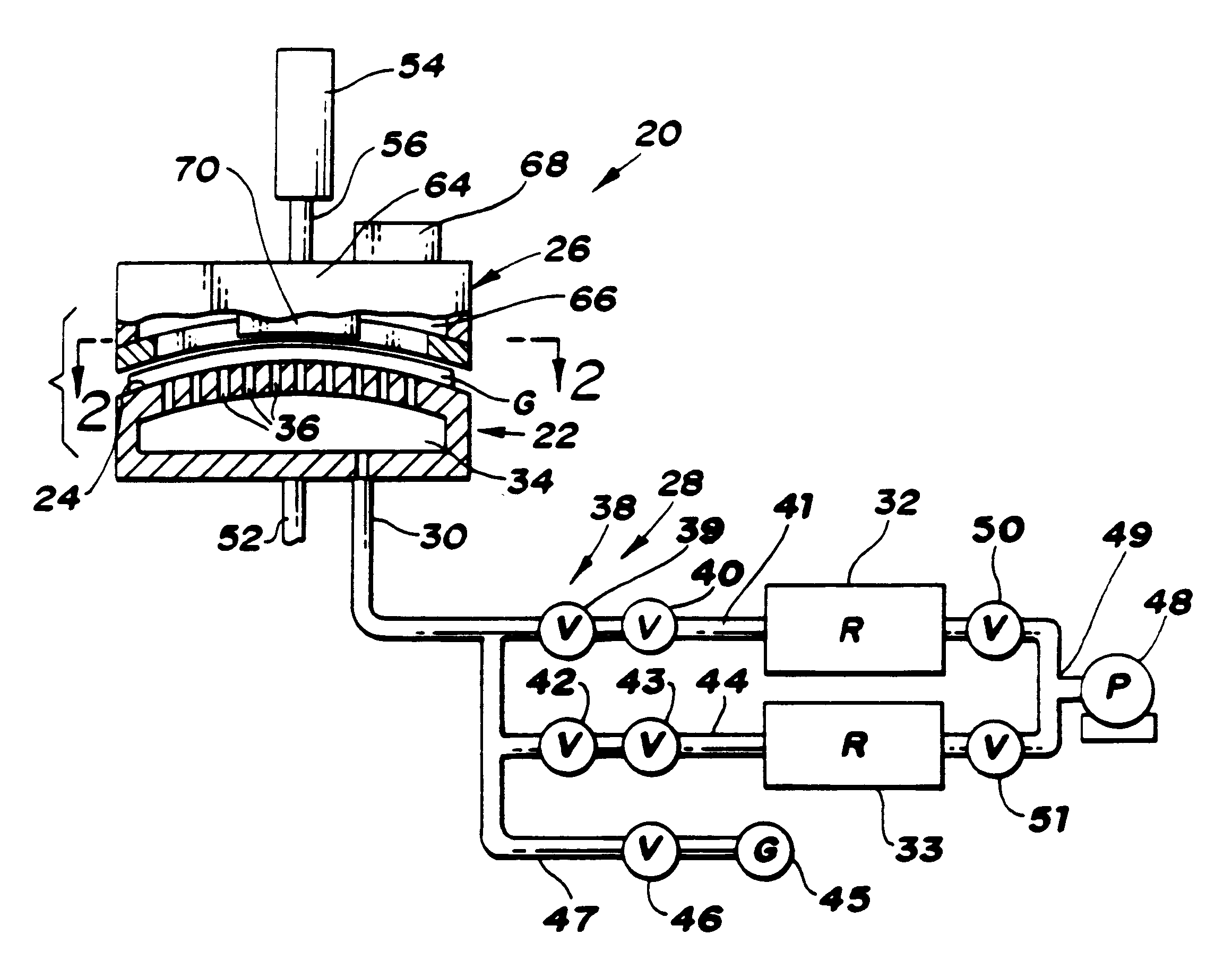
In carrying out the above object and other objects of the invention, apparatus for forming a heated glass sheet having a periphery includes a vacuum mold having a full surface that defines a shape to which the glass sheet is to be formed and also includes a peripheral mold for forming and sealing the periphery of the glass sheet against the surface of the vacuum mold to provide a sealed periphery of the glass sheet. A vacuum system of the apparatus: including at least one vacuum reservoir, conducting including at least one conduit for communicating the vacuum reservoir and the vacuum mold within the sealed periphery of the glass sheet, and valving including at least one valve located between the vacuum reservoir and the vacuum mold and operable to (a) initially communicate the vacuum mold surface within the sealed periphery of the glass sheet with at least one vacuum reservoir to provide a vacuum impulse in the range of 0.1 to 0.7 atmospheres of vacuum to elastically form the glass sheet to the shape of the vacuum mold surface; and (b) thereafter terminates the vacuum impulse at a predetermined time so as to reduce optical distortion of the heated glass sheet as a result of engagement with the vacuum mold surface.
In carrying out the above mentioned object and other objects of the invention, the method for forming a heated glass sheet by the apparatus includes sealing the periphery of the glass sheet against a full surface vacuum mold and communicating the vacuum mold surface within the sealed periphery of the glass sheet with at least one vacuum reservoir to provide a vacuum impulse in the range of 0.1 to 0.7 atmospheres of vacuum to elastically form the glass sheet to the shape of the vacuum mold surface, and the vacuum impulse is thereafter terminated at a predetermined time so as to reduce optical distortion of the hot glass sheet as a result of engagement with the mold surface.

Problems solved by technology

More specifically, the vacuum drawn at the vacuum mold surface within the sealed periphery of the glass sheet is large enough to fully form the glass sheet to the shape of the mold surface but is not applied long enough to overcome the large viscous characteristics of the glass such that reduced optical distortion results at the interface of the glass sheet and the mold.

Method used


Image

  • Apparatus for vacuum impulse forming of heated glass sheets
  • Apparatus for vacuum impulse forming of heated glass sheets
  • Apparatus for vacuum impulse forming of heated glass sheets

Examples


Embodiment Construction

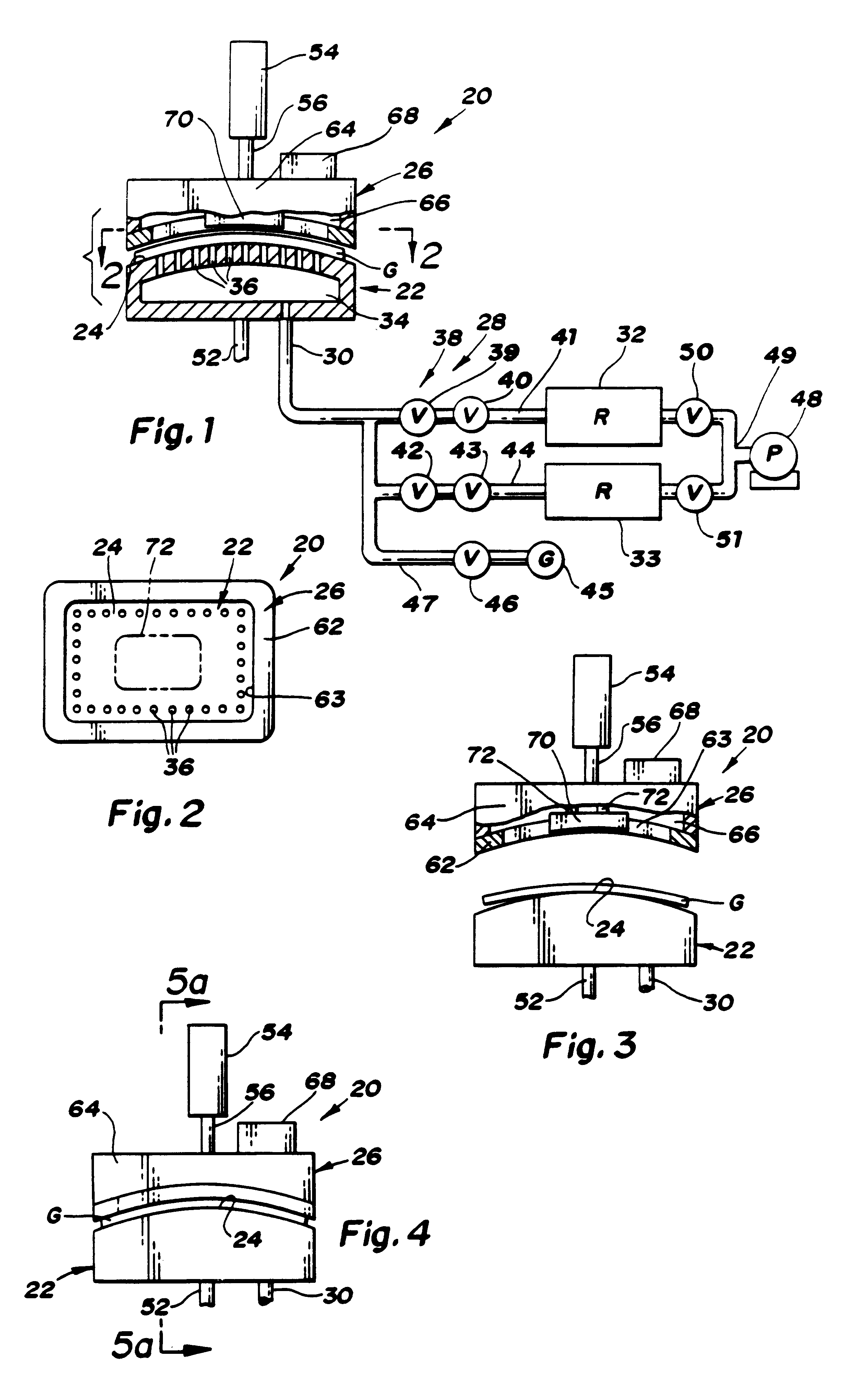
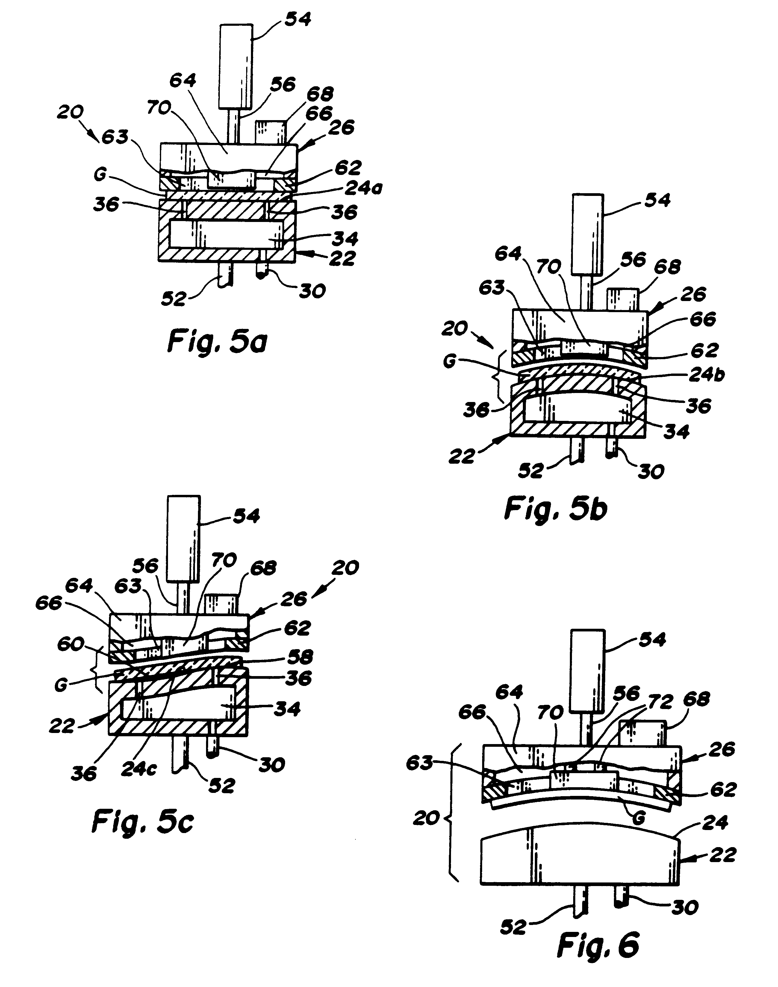
With reference to FIG. 1 of the drawings, one embodiment of apparatus 20 for forming a heated glass sheet G in accordance with the present invention includes a vacuum mold 22 having a full surface 24 that defines a shape to which the glass sheet is to be formed. A peripheral mold 26 of the apparatus provides forming and sealing of the periphery of the glass sheet against the surface 24 of the vacuum mold 22 as is hereinafter more fully described. A vacuum system 28 of the apparatus has a conduit 30 that provides a preferred means for communicating the vacuum mold surface 24 within the sealed periphery of the glass sheet with at least one vacuum reservoir which is illustrated as a first vacuum reservoir 32, and preferably also with a second vacuum reservoir 33, to provide a vacuum impulse in the range of 0.1 to 0.7 atmospheres of vacuum to elastically form the glass sheet to the shape of the vacuum mold. This vacuum impulse provides a much greater extent of vacuum than with conventio...


PUM

PropertyMeasurementUnit
Timeaaaaaaaaaa
Timeaaaaaaaaaa
Pressureaaaaaaaaaa

Abstract

Apparatus (20,120) for forming a heated glass sheet G is disclosed as including a vacuum mold (22,22a,122,122a) having a full surface (24,24a,124,124a) against which a peripheral mold (26,26a,126,126a) presses the glass sheet periphery and with which at least one vacuum reservoir (32,33) is communicated within the interior of the sealed glass sheet periphery to form the glass sheet to the shape of the vacuum mold surface. Valving (38) of a vacuum system (28) is preferably operable to provide the vacuum impulse in two stages with an initial limited extent of vacuum and a subsequent greater extent of vacuum by communication first with one vacuum reservoir (32) and subsequently with another vacuum reservoir (33). Different embodiments of the vacuum mold have the vacuum mold surface facing upwardly and downwardly with convex and concave shapes. Glass sheet shapes including straight line elements such as cylindrical and conical bends as well as shapes including curvatures in transverse directions and inverse curvatures can be effectively provided by this vacuum impulse forming.

Description

This invention relates to vacuum forming of heated glass sheets.Vacuum forming of heated glass sheets against a curved mold surface has been performed for many years. Such vacuum forming is usually performed by drawing a vacuum within openings in the mold surface. The extent of vacuum utilized is normally on the order of about several to 10 inches (about 10 to 25 cm.) water column. Such a conventional vacuum can be provided by commercially available hot operating fans that are positioned within a heated environment in which the vacuum forming is performed and can also be provided by a gas jet pump such as disclosed by U.S. Pat. No. 4,222,763 McMaster wherein a primary gas flow is introduced into a passageway through jet openings which have axial and circumferential components that are substantially tangent to the inner surface of the passageway such that the primary gas flow induces a secondary gas flow that generates the vacuum through suitable communication passageways.Prior art g...

Claims


Application Information

Patent Timeline
IPC IPC(8): C03B23/03C03B23/02C03B23/035B25J15/06
CPCC03B23/03C03B23/0305C03B23/0357
Inventor SHETTERLY, DONIVAN M.HERSCH, CHRISTOPHER A.
Owner GLASSTECH
Learn More