
Shutter box for a window or door

Inactive Publication Date: 2001-05-15
SCHUCO INT KG
View PDF14 Cites 34 Cited by
  • Summary
  • Abstract
  • Description
  • Claims
  • Application Information

AI Technical Summary

Benefits of technology

is to develop the shutter box in such a way that the risk of damage to the individual sections is avoided and the shutter box may be manufactured quickly, easily and inexpensively.
For further increasing the strength of the shutter box or the rigidity of the individual sections, according to a further embodiment reinforcing or stabilizing elements may be disposed in the individual sections. These may be, for example, inlaid rods or strips made of metal or plastic material.

Problems solved by technology

This is expensive and laborious.
The result is that often incorrectly fitting screw connections and accordingly incorrectly fitting shutter boxes are produced or, because of the extreme time pressure, the points provided in the plastic material for receiving the metal screws are damaged with the result that the individual section may no longer be used.

Method used


Image

  • Shutter box for a window or door
  • Shutter box for a window or door
  • Shutter box for a window or door

Examples


Embodiment Construction

with reference to drawings which merely show embodiments. The drawings show:

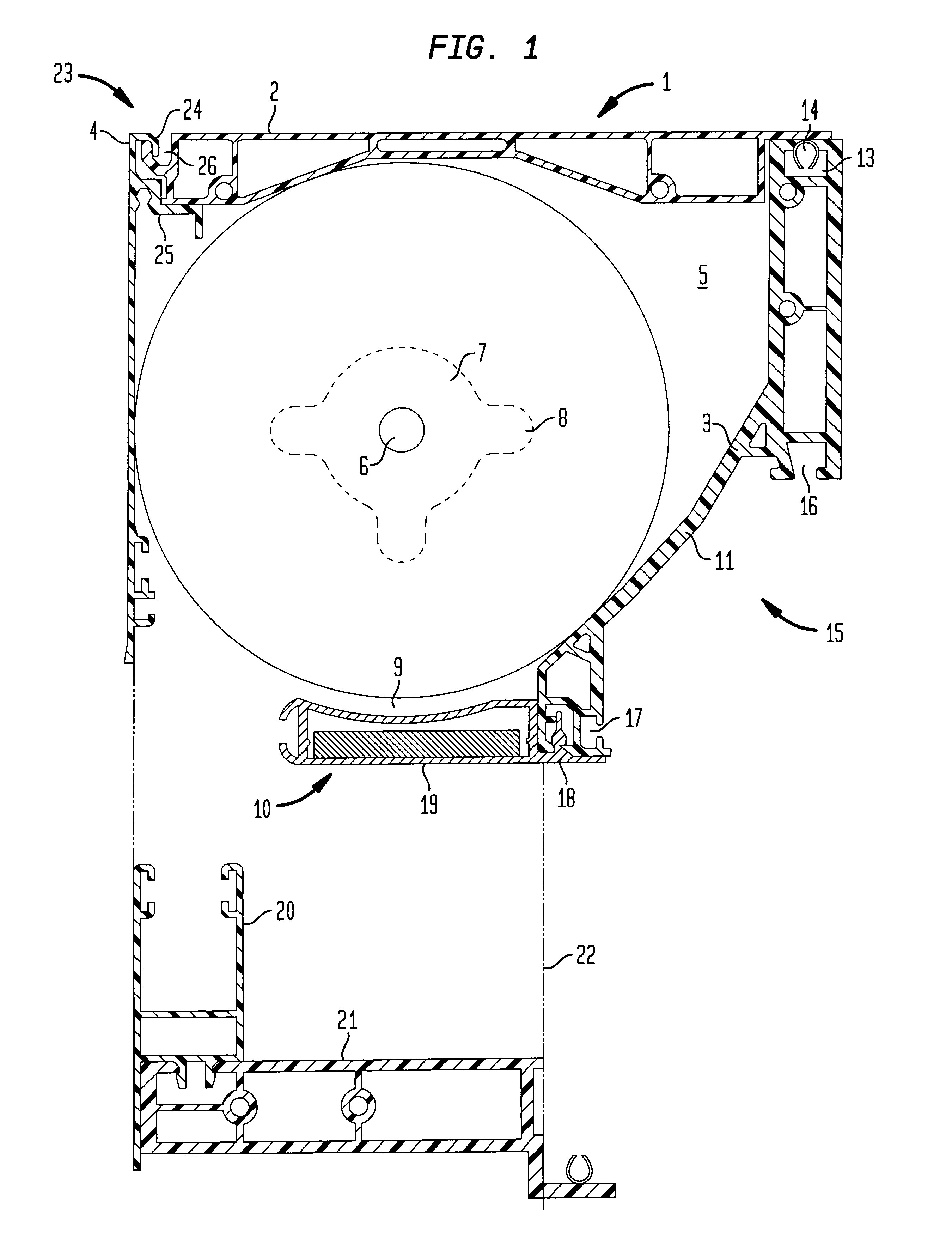
FIG. 1 is a diagrammatic, part-sectional view of a first embodiment of a shutter box according to the invention; and

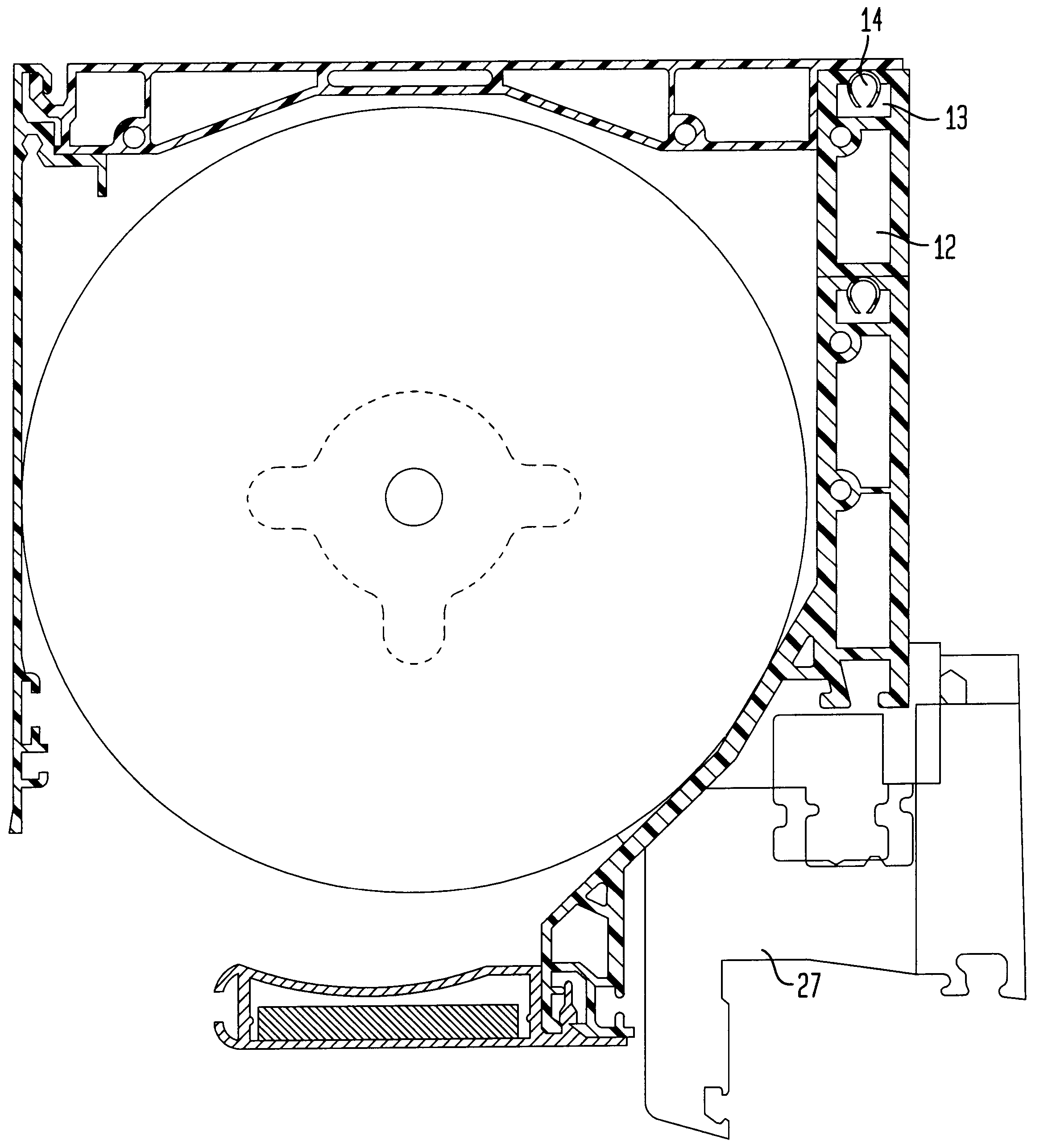
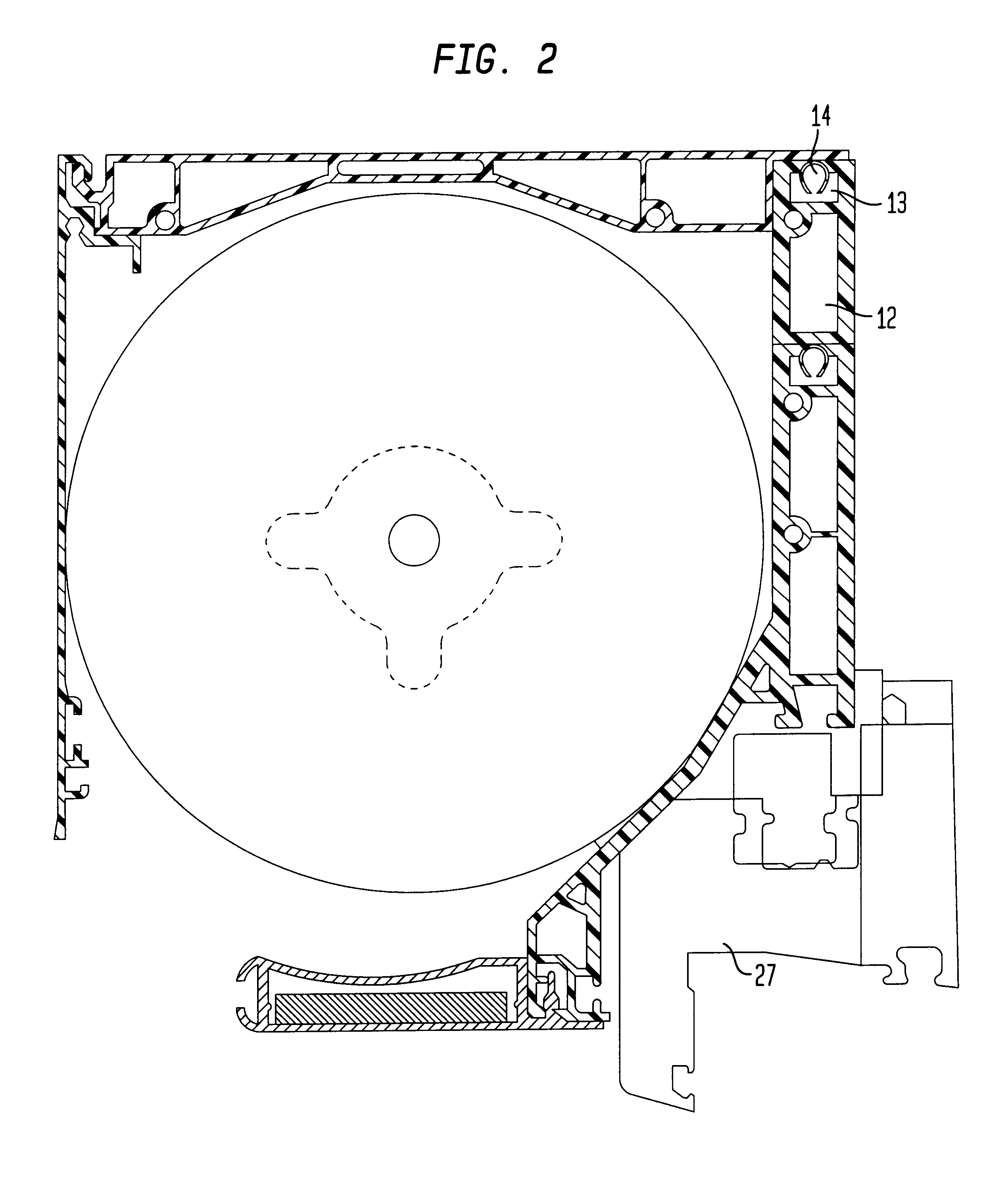
FIG. 2 is a shutter box supplemented by an additional web.

DETAILED DESCRIPTION OF A PREFERRED EMBODIMENT

In FIG. 1, the reference character 1 quite generally denotes a shutter box having a top part or top cover 2, an angle section bar 3, an outer panel 4 and a side wall 5.

Inside the shutter box 1, an armoured shutter (not shown) is wound on a centrally provided take-up shaft 6, the take-up shaft being supported by two bearing blocks 7 which are fastened by the diagrammatically illustrated fastening means 8 to the shutter box.

Provided in the region below the take-up shaft is an opening 9 which may be made accessible for repair or maintenance purposes by removal of the plate 10 which is fastened to the angle section bar 3.

The angle section bar 3 closes off the rear of the shutter box 1 and simulta...


PUM


Abstract

A shutter box for a door having a leaf includes a top cover, and an angle section bar having an outward and upward leading wall portion and a substantially vertical portion extending to the top cover. The leading wall portion is connected directly to the vertical portion and forms an oblique angle therebetween. The shutter box is assembled utilizing exclusively engageable snaps and attachable to the door by engageable snaps, with the leading wall portion of the angle section bar arranged substantially parallel to an obliquely extending portion of the leaf of the door, when the door is in a closed state.

Description

1. Field of the InventionThe present invention relates to a shutter box for a window or door, the bottom region of which simultaneously takes the form of a top transverse spar of the fixed frame, against which the casement of the window or leaf of the door strikes, and the transverse spar simultaneously takes the form of an angle section bar with an obliquely outward and upward leading wall portion and an extensively vertical web extending up to the top cover of the shutter box.2. Description of the Related ArtSuch a shutter box is known from German Utility Model DE 92 01 336 U1. To manufacture said known shutter box, individual sections are produced which then have to be assembled by means of screw connections to form the shutter box. A plastic material is frequently used to manufacture the individual sections; the individual sections made of said material are connected to one another by screws made of metal. This is expensive and laborious. Such a shutter box is however a mass-pro...

Claims


Application Information

Patent Timeline
IPC IPC(8): E06B9/17
CPCE06B9/17023
Inventor REICHERT, RAINER
Owner SCHUCO INT KG
Learn More