Planar illumination device

a planar illumination and sidelight technology, applied in the direction of planar/plate-like light guides, lighting and heating apparatus, instruments, etc., can solve the problems of uneven brightness of the planar illumination device, lowered light use efficiency, and difference in light reflectance between both, so as to achieve excellent radiation performance of heat, efficient radiation effect, and easy integral formation

Inactive Publication Date: 2009-12-24
MINEBEAMITSUMI INC
View PDF5 Cites 3 Cited by
  • Summary
  • Abstract
  • Description
  • Claims
  • Application Information

AI Technical Summary

Benefits of technology

[0020]Also, the inner frame is formed from a white resin material, while the outer frame is preferably formed from a heat conductive metal material, by which the elastic action portion according to the present invention can be easily formed integrally, and the planar illumination device can be realized, provided with the inner frame capable of efficiently reflecting the leakage light from the side end face of the light guide plate and returning it to the light guide plate and ...

Problems solved by technology

Therefore, light leaking from the terminal end face 103b cannot be efficiently reflected to the light guide plate 103, which causes a problem of lowered use efficiency o...

Method used


Image

  • Planar illumination device
  • Planar illumination device
  • Planar illumination device

Examples


first embodiment

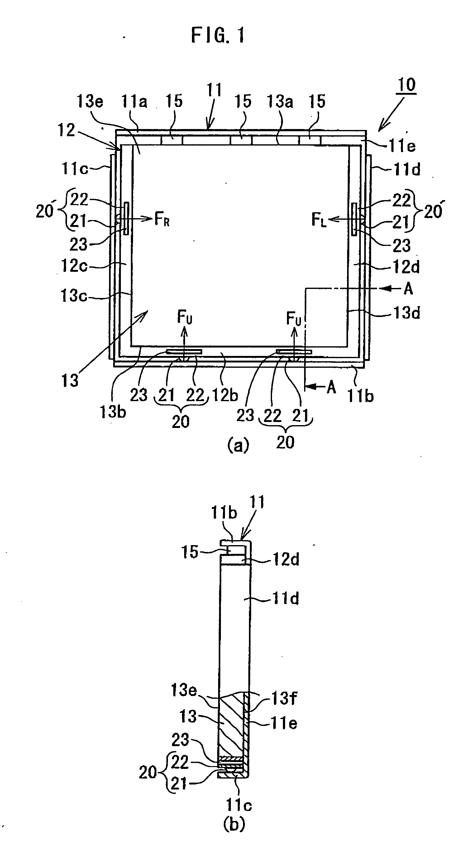
[0035]FIG. 1 is a view illustrating an essential part of a planar illumination device 10 in the present invention, in which FIG. 1A is a top view and FIG. 1B is a side view illustrating a part as an A-A section. The planar illumination device 10 in this embodiment comprises a light guide plate 13, a point-like light source 15 arranged on a side end face 13a of the light guide plate 13, and frames 11, 12 holding them, and the frame comprises an inner frame 12 formed in the U-shape on a top view and an outer frame 11 having a plane-state seat portion 11e and side walls 11a, 11b, 11c, 11d installed upright on an outer edge portion of the seat portion 11e. In the planar illumination device 10, the light guide plate 13 is accommodated in the inner frame 12 and mounted on the seat portion 11e of the outer frame 11 together with the inner frame 12, and the point-like light sources 15 are arranged along the side end face (incoming-light face) 13a on the open side of the inner frame 12 in th...

second embodiment

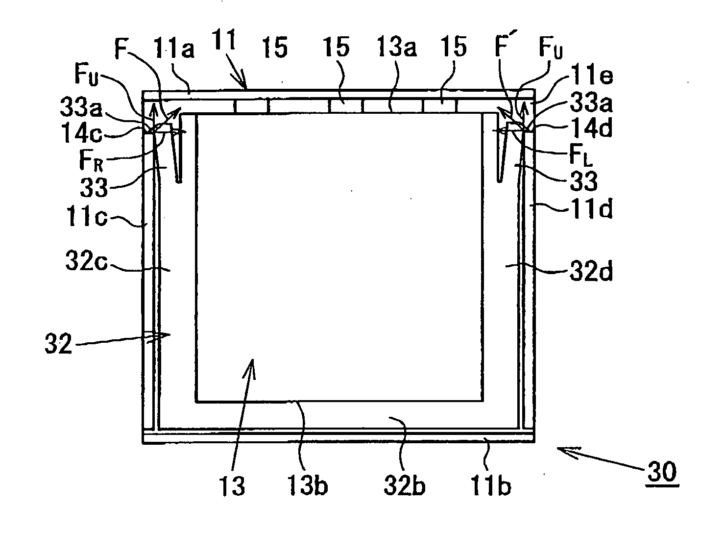
[0046]Next, the planar illumination device in the present invention will be described. FIG. 2 is a top view illustrating an essential part of the planar illumination device 30. The planar illumination device 30 in this embodiment has configuration basically similar to that of the planar illumination device 10 shown in FIG. 1, and only the configuration of the elastic action portion 33 provided at the inner frame 32 is different. Thus, description on the duplicated portions will be omitted and the configuration and actions of the elastic action portion 33 will be described in detail.

[0047]In the planar illumination device 30, the elastic action portion 33 comprises a pair of cantilever beams 33 provided at opposing two sides 32c, 32d of the inner frame 32, the cantilever beam 33 extending with inclination from each of the sides 32c, 32d of the inner frame toward a free end 33a on the open side of the inner frame 32 so as to expand outward of the inner frame 32, and at the free end (d...


PUM


Abstract

A planar illumination device comprises a light guide plate, a point-like light source arranged on an incoming-light face of the light guide plate, an inner frame formed substantially in a U-shape on a top view, and an outer frame having a seat portion and side walls wherein the light guide plate is accommodated in the inner frame and mounted on the seat portion of the outer frame, while the point-like light source is arranged along the incoming-light face of the light guide plate and held between the incoming-light face and the side wall of the outer frame. At the inner frame, an elastic action portion which is elastically deformed so as to make a partial contact with the outer frame and energizes the light guide plate toward the point-like light source is provided.

Description

TECHNICAL FIELD[0001]The present invention relates to a side-light-type planar illumination device and particularly to a planar illumination device used as illuminating means of a liquid crystal display device.BACKGROUND ART[0002]As an auxiliary light source for a liquid crystal display device used for a cellular phone or the like, a side-light type planar illumination device in which a primary light source is arranged on a side end face of a light guide plate is mainly used (hereinafter the side end face on which the primary light source is arranged is also called as a incoming-light face). As the primary light source of a side-light-type planar illumination device, a cold-cathode tube lamp has been used, but currently, a point-like light source such as a white LED which is more excellent in handling, easier in size reduction and better in impact resistance than the cold-cathode tube lamp is used in many cases. Application fields of the planar illumination device using such a point...

Claims


Application Information

Patent Timeline
IPC IPC(8): F21V7/22
CPCG02B6/0068G02B6/0091G02B6/0085
Inventor OHNO, YASUO
Owner MINEBEAMITSUMI INC
Why Eureka
Try Eureka