Plastic washing fluid container for a washing machine

a technology of washing machine and washing fluid, applied in the direction of other washing machines, cleaning using liquids, textiles and paper, etc., can solve the problem of significant complexity if the layout, design or geometry of detecting the air within the trap needs modification

Inactive Publication Date: 2006-06-01
MIELE & CIE KG
View PDF6 Cites 4 Cited by
  • Summary
  • Abstract
  • Description
  • Claims
  • Application Information

AI Technical Summary

Benefits of technology

[0014] In a useful embodiment the housing of the air trap is formed of a lower housing section and an upper housing section with the downwardly open lower housing section being integrally formed in, and penetrating through, the wall of the washing fluid container cap. The internal chamber of the air trap is thus accessible from the exterior because the upper housing section is mounted for movement relative to the lower housing section at the outer surface of the washing fluid container cap. Accordingly, the interior of the housing of the air trap is easily accessible for cleaning.
[0015] Advantageously, the upper housing section is integrally connected to the lower housing section by means of a hinge of flexible film or foil which makes possible the fabrication of both housing sections in one injection molding tool. In such an arrangement the upper housing section is pivotally connected to the lower housing section by the foil hinge so that the cap of the washing fluid container and the two housing sections may be molded in one piece. This yields two advantages: The air trap is integrally formed in the cap of the washing fluid container and as a result of the foil-hinge connection the interior of the air trap is rendered accessible.

Problems solved by technology

The disadvantage inherent in the devices of the mentioned prior art is not only that on the one hand the air traps are mounted as a separate components on the cap of the washing fluid container involving, on the other hand and particularly in the case of the air trap being mounted on the cylindrical drum, significant complexity if layout, design or geometry of detecting the air within the trap requires modification.

Method used


Image

  • Plastic washing fluid container for a washing machine
  • Plastic washing fluid container for a washing machine
  • Plastic washing fluid container for a washing machine

Examples


Embodiment Construction

[0025]FIG. 6 is a schematic lateral sectional view showing a washing machine 30 provided with a washing fluid container 1. The washing fluid container 1 consist of a cylindrically structured receptacle 2 which surrounds a drum 31. The cylindrical receptacle 2 is closed by at least one front wall or cap 3.

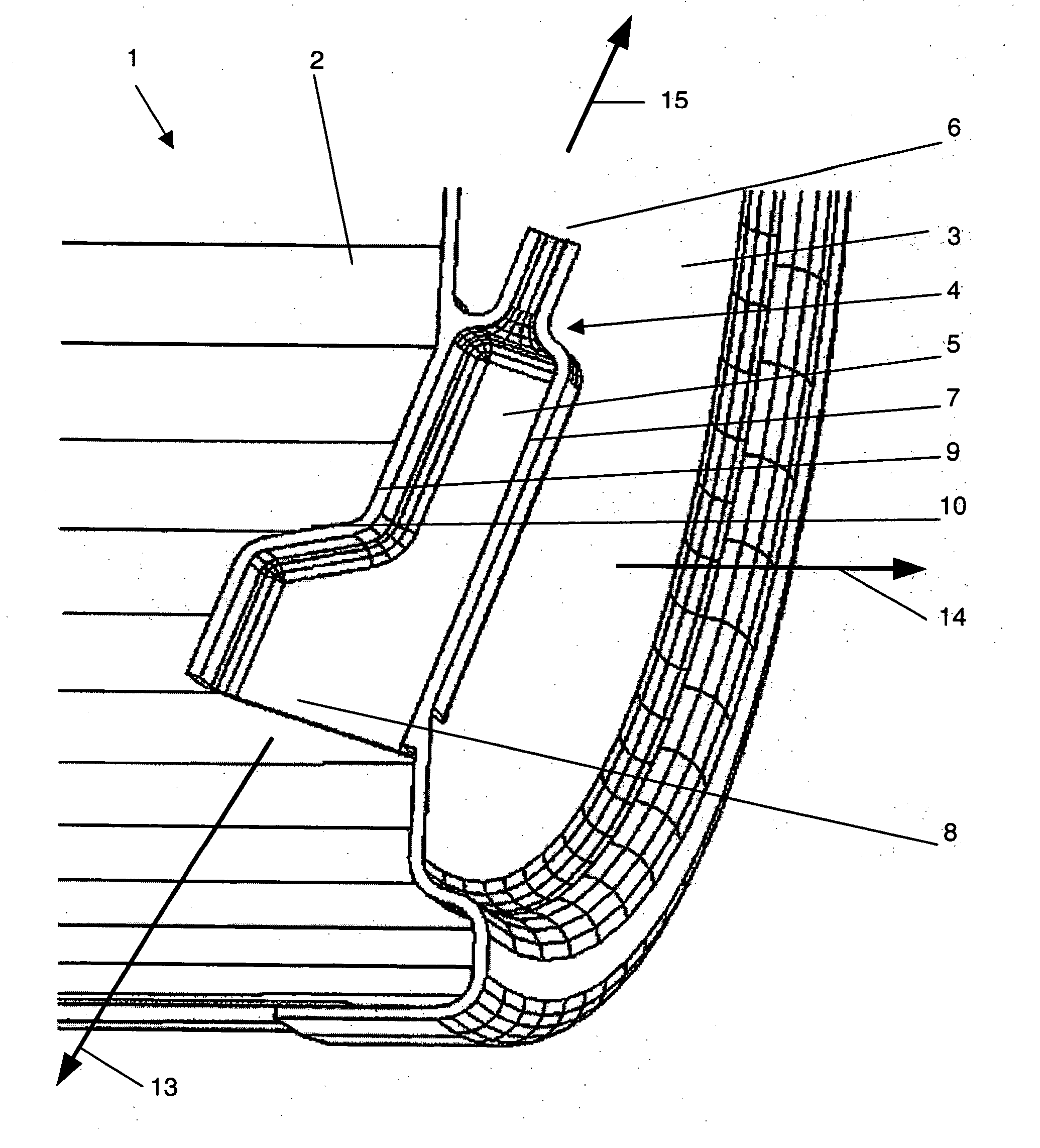
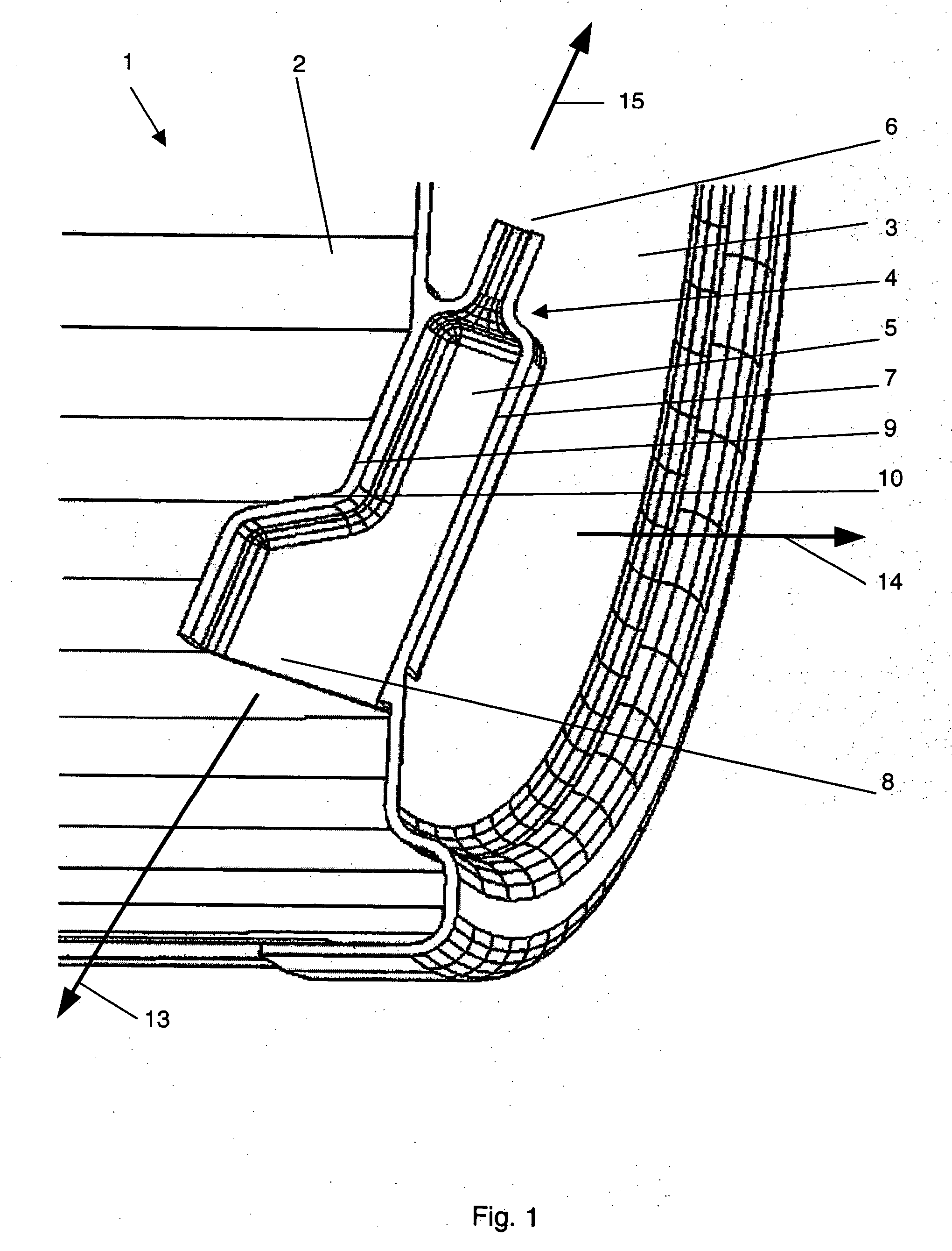
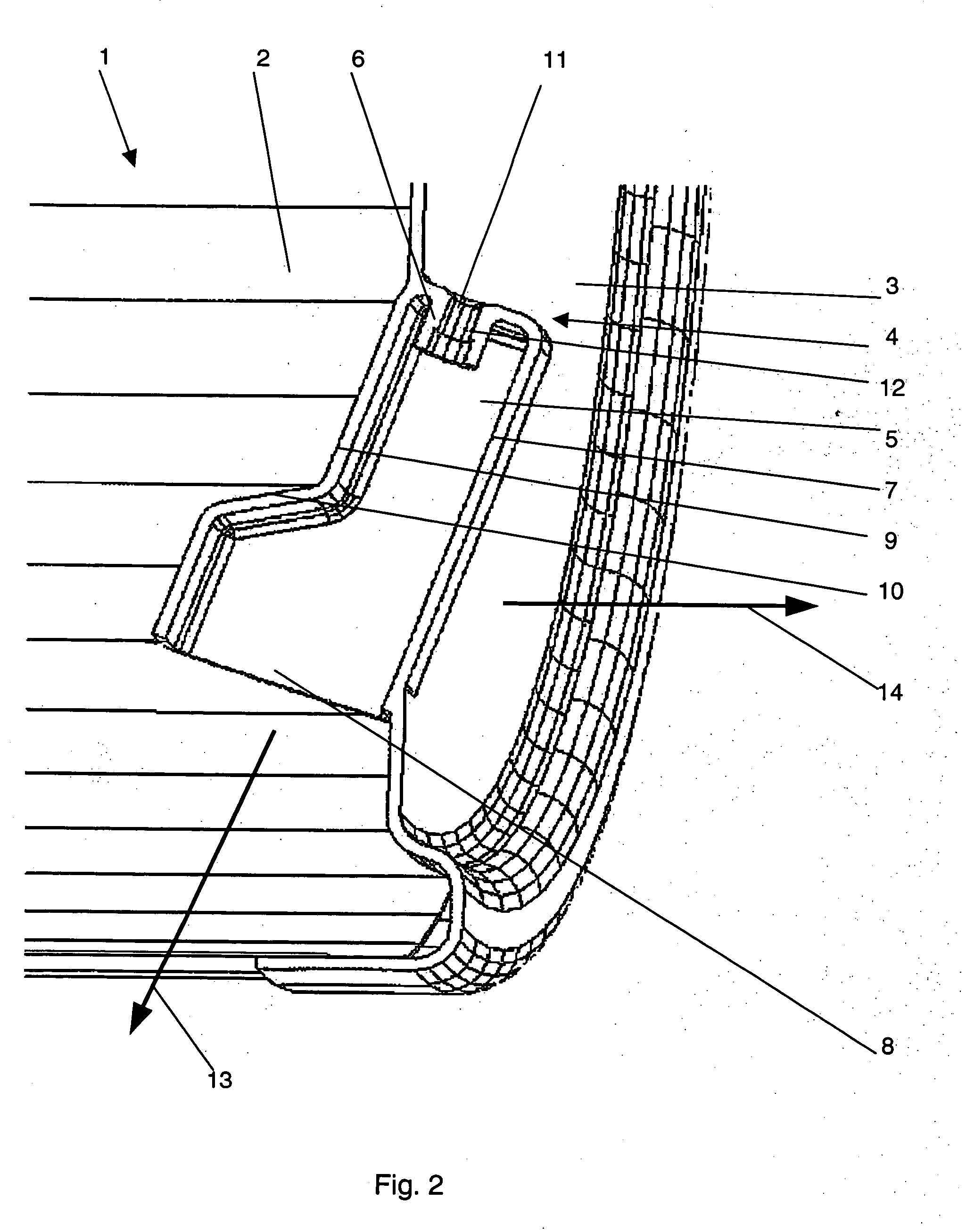
[0026]FIGS. 1 and 2 depict a section of a washing fluid container 1 made of plastic. At each end of the receptacle 2 there is provided a structured washing fluid container cap 3. As may be seen in FIGS. 1 and 2, one of the washing fluid container caps 3, which may have been retrofitted to the receptacle 2, is provided with an air trap 4 for measuring the level of washing fluid. The air trap 4 has a housing 5 which opens in a downward direction and which at its upper end is provided with an opening nipple 6 for a measuring hose (not shown). As will be understood by those skilled in the art and as indicated supra, the hose is connected to a gage (not shown) or the like for deriving a...


PUM


Abstract

A washing fluid container of substantially cylindrical configuration having at least one open end closed by a cover provided with an integrally formed air trap penetrating the cover at an acute angle with a first housing section extending at an acute angle upwardly of the surface of the cover outside of the container and a second housing section extending at an acute angle downwardly of the surface of the cover inside of the cover, the second housing section being adapted to receive washing fluid therein and the first housing section being provided with means responsive to washing fluid in the second housing section.

Description

BACKGROUND OF THE INVENTION [0001] 1. Field of the Invention [0002] The invention, in general, relates to a plastic washing fluid container, hereafter sometimes referred to as a tub, for a washing machine and, more particularly, to a tub surrounding a cylindrical drum each end of which is provided with a closure cap at least one of which has an air trap for measuring the washing fluid level and which at its lower and upper ends is respectively provided with an opening and a nipple for receiving a hose. [0003] 2. The Prior Art [0004] Such well-know air traps are used for measuring the level of washing fluid which at different operational cycles of the washing machine is either plain water or water with a detergent dissolved therein, in a washing machine drum. As washing fluid rises within the air trap it causes the air entrapped therein to be compressed. The pressure of the compressed air is a measure of the level of washing fluid. Thus, German patent specification No.: DE 196 46 440...

Claims


Application Information

Patent Timeline
Patent Type & Authority Applications(United States)
IPC IPC(8): D06F39/12
CPCD06F37/262D06F37/266D06F39/087
Inventor BROCKSCHMIDT, EGONHOLLENHORST, MATTHIASNIEDER, ANTJE
Owner MIELE & CIE KG
Why Eureka
Try Eureka