
Absorption information measuring method and apparatus of scattering medium

a scattering medium and absorption information technology, applied in the direction of optical radiation measurement, diagnostic recording/measuring, instruments, etc., can solve the problems of inability to accurately measure the concentration of specific absorption constituents inside, inability to use light to non-invasively measure the living body, and require an extremely long calculation tim

Inactive Publication Date: 2001-05-15
HAMAMATSU PHOTONICS KK
View PDF9 Cites 111 Cited by
  • Summary
  • Abstract
  • Description
  • Claims
  • Application Information

AI Technical Summary

Problems solved by technology

These conventional technologies, however, are not yet capable of accurately measuring the concentration of the specific absorptive constituent inside for tissues and organs having various shapes like the living body or for objects having individual differences of shape though being tissues or organs of a same kind.
This presents a serious problem for non-invasive measurements of living body utilizing light, and improvements therein are strongly desired.
The Monte Carlo simulations, however, require an extremely long calculation time and do not allow calculation of a concentration of a specific absorptive constituent inside the scattering medium from their results.
As a result, use of approximate boundary conditions is indispensable to measurements of living tissues having complicated shapes, which is a cause to produce large measuring errors.
As described above, there are no methods for measuring absorption information sufficient to be systematically applied to scattering media of different shapes, and it was extremely difficult for conventional technologies to systematically accurately and efficiently measure the concentration of a specific absorptive constituent or the like in the scattering media of different shapes.

Method used


Image

  • Absorption information measuring method and apparatus of scattering medium
  • Absorption information measuring method and apparatus of scattering medium
  • Absorption information measuring method and apparatus of scattering medium

Examples


embodiment 1

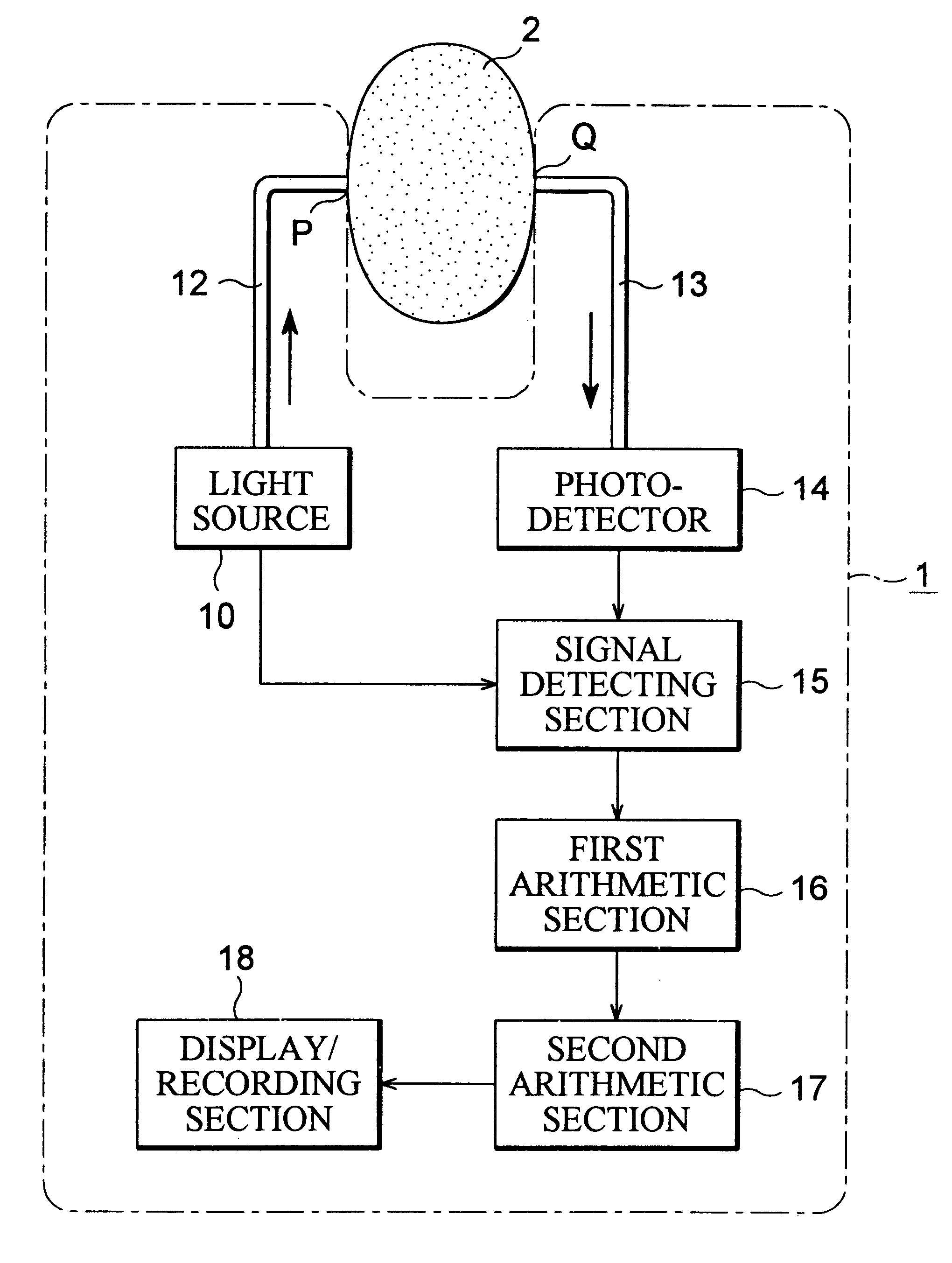
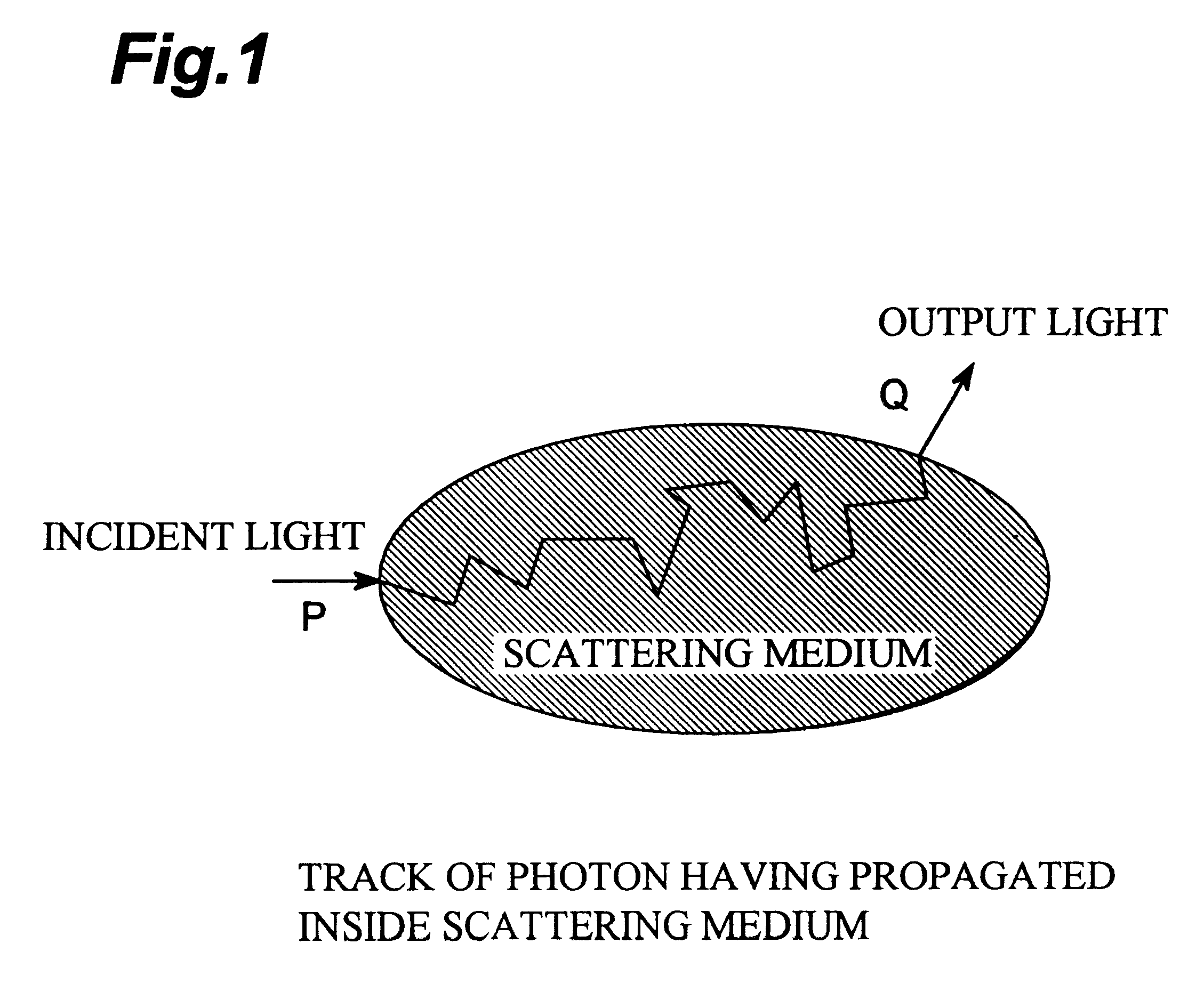
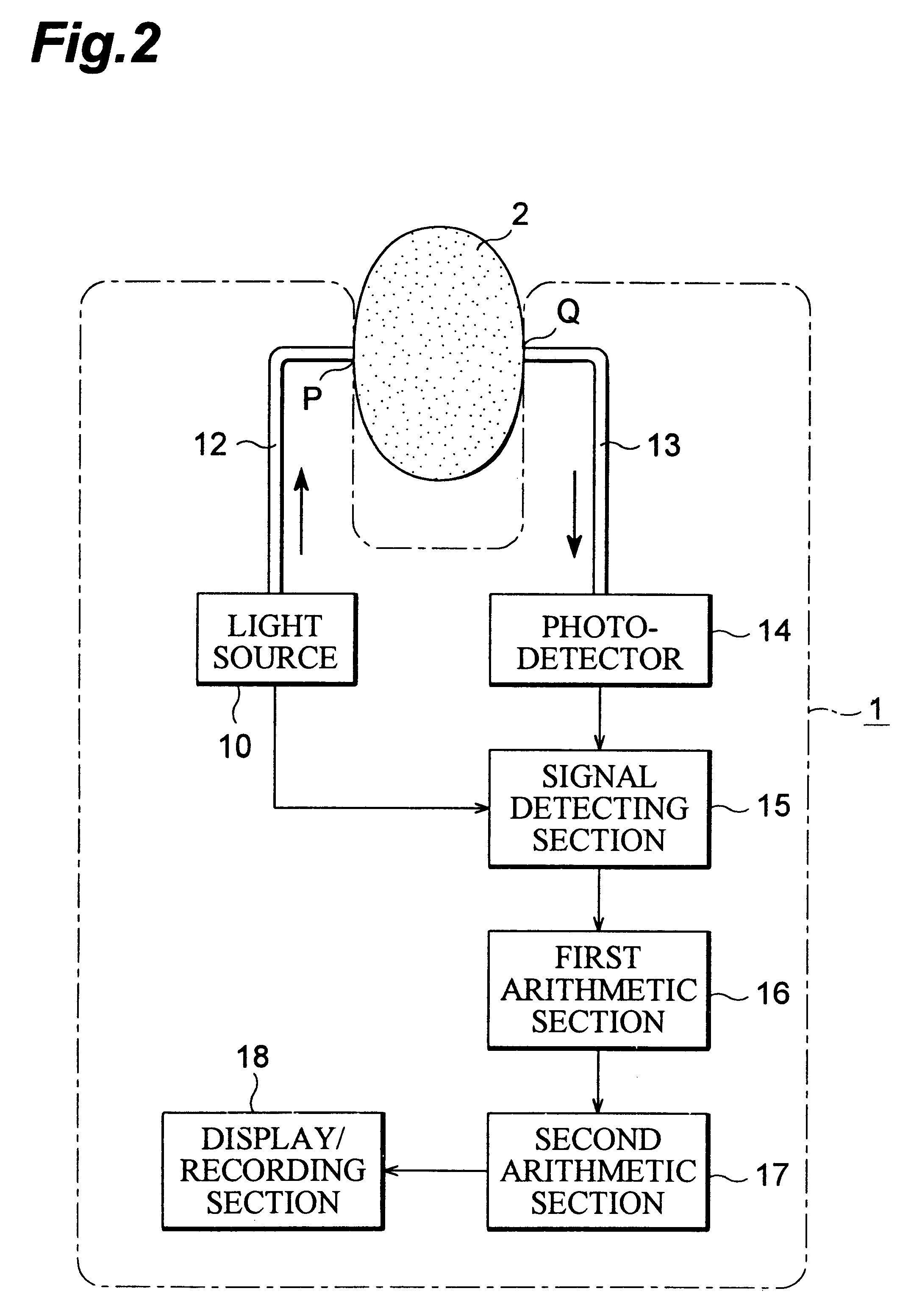
FIG. 2 shows the first embodiment of the apparatus of the present invention for carrying out the method of the present invention and illustrates the configuration of apparatus 1 for measuring the temporal change of concentration of absorptive constituent inside scattering medium 2. In this configuration of apparatus 1, modulated light of predetermined wavelength .lambda. and modulation frequency f (the modulation angular frequency .omega.=2.pi.f) is made incident on position P (light incidence position) in the surface of scattering medium 2 and the light having propagated inside the scattering medium 2 is received at another position Q (photodetection position) in the surface. Then a change in the concentration of an absorptive constituent inside the scattering medium is quantified by repetitively carrying out measurements. In this case, the change in the concentration of the absorptive constituent can be quantified by taking a concentration of the absorptive constituent in the firs...

embodiment 2

Measurements are carried out in the same manner as in above Embodiment 1 except for synchronous scanning of the light incidence position P and photodetection position Q of the modulated light relative to the scattering medium 2, and the reference value is a concentration of the absorptive constituent at an arbitrary position, whereby a spatial distribution of concentration difference from the reference value can be measured. Also in this case, similarly as in above Embodiment 1, the spatial distribution of difference of concentration of absorptive constituent from the reference value can be measured using Eqs. (7.1) to (7.4).

FIG. 7 shows the second embodiment of the apparatus of the present invention for carrying out the method of the present invention and illustrates the configuration of apparatus 1 (mammography) for measuring the spatial distribution of concentration of absorptive constituent inside the scattering medium 2 like the breast. In FIG. 7 the components having the same ...

embodiment 3

FIG. 8 shows the third embodiment of the apparatus of the present invention for carrying out the method of the present invention and illustrates the configuration of the apparatus for measuring the concentration of absorptive constituent inside the scattering medium 2. In FIG. 8 the components having the same functions as those in FIG. 2 associated with the first embodiment and in FIG. 7 associated with the second embodiment are denoted by the same symbols. This configuration is arranged to use the modulated light of two wavelengths .lambda..sub.1 and .lambda..sub.2 and two photodetection distances r.sub.1 and r.sub.2. In this case, Eq. (15) described previously holds for each of measurements at the two photodetection distances r.sub.1 and r.sub.2. Accordingly, the difference between the absorption coefficients of the measured scattering medium 2 for the light of two wavelengths, .mu..sub.a2 -.mu..sub.a1, can be obtained by eliminating the coefficient b.sub.2 / b.sub.1 in Eq. (15) fr...


PUM


Abstract

A method characterized by making modulated light having a predetermined modulation frequency component, incident to a scattering medium, receiving the modulated light having propagated inside the scattering medium to acquire measurement signals, detecting signals of the foregoing modulation frequency component from the measurement signals, obtaining amplitudes and inclinations of phase against modulation angular frequency, of the signals of the foregoing modulation frequency component, calculating a difference between absorption coefficients being primary information, based on a predetermined relation among the amplitudes, the inclinations of phase against modulation angular frequency and the difference between absorption coefficients, and calculating a difference of concentration of an absorptive constituent being secondary information, based on the difference between absorption coefficients.

Description

1. Field of the InventionThe present invention relates to a method and an apparatus for measuring absorption information of a scattering medium and, more particularly, to a method and apparatus for measuring a temporal change or a spatial distribution of concentration of an absorptive constituent in a scattering medium having non-reentrant surfaces. The invention further concerns a method and apparatus for measuring a concentration of an absorptive constituent inside the scattering medium by use of light of plural wavelengths.2. Related Background ArtThere are very strong demands for non-invasive and precise measurements of absorption information including a concentration of a specific absorptive constituent inside a scattering medium like a living body, a temporal change or a spatial distribution thereof, and so on. Attempts of various methods have been made heretofore, including methods using continuous wave light (cw light) and modulated light (for example, pulsed light, square-w...

Claims


Application Information

Patent Timeline
IPC IPC(8): G01N21/47G01N21/49G01N21/31G01J1/00G01J1/04
CPCG01N21/49
Inventor TSUCHIYA, YUTAKA
Owner HAMAMATSU PHOTONICS KK
Learn More