Sensorless control apparatus and method for induction motor

a sensorless control and induction motor technology, applied in the direction of motor/generator/converter stopper, dynamo-electric converter control, dynamo-electric gear control, etc., can solve the problems of reducing load capability and flux-weakening method not being applicable in some heavy-load applications

Active Publication Date: 2009-06-25
DELTA ELECTRONICS INC
View PDF20 Cites 26 Cited by
  • Summary
  • Abstract
  • Description
  • Claims
  • Application Information

AI Technical Summary

Problems solved by technology

However, the flux weakening will decrease the load capability, so that the flux-weakening method is not applicable for some heavy-load application.

Method used


Image

  • Sensorless control apparatus and method for induction motor
  • Sensorless control apparatus and method for induction motor
  • Sensorless control apparatus and method for induction motor

Examples


first embodiment

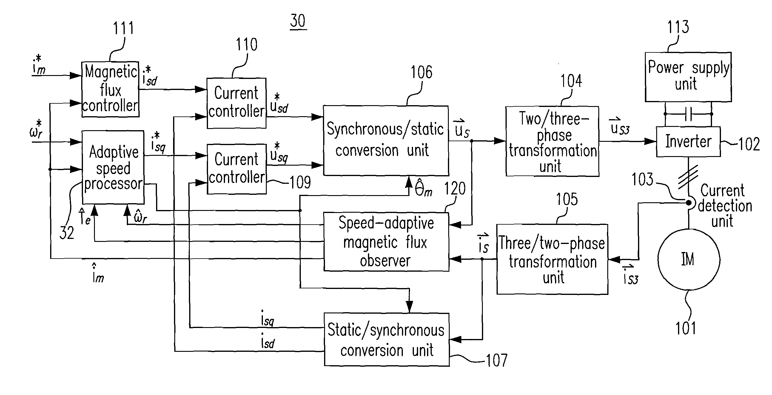
[0039]Please refer to FIG. 4, which is a schematic diagram showing a sensorless control system for the induction motor according to the present invention. As shown, the sensorless control system 30 includes the power supply unit 113, the inverter 102, the induction motor 101, the current detection unit 103, the three / two-phase transformation unit 105, the two / three-phase transformation unit 104, a speed-adaptive magnetic flux observer 120, the magnetic flux controller 111, an adaptive speed processor 32, the static / synchronous conversion unit 107, the current controller 109, the current controller 110, and the synchronous / static conversion unit 106.

[0040]The power supply unit 113 provides a DC bus voltage to the inverter 102. The inverter 102 receives a three-phase control voltage {right arrow over (U)}s3 and the DC bus voltage and uses the three-phase control voltage {right arrow over (u)}s3 to control the DC bus voltage for driving the induction motor 101 coupled to the inverter 1...

second embodiment

[0052]Please refer to FIG. 6, which is a schematic diagram showing a sensorless control system for the induction motor according to the present invention. The control system 40 in FIG. 6 is an expansion of the control system 30 in FIG. 4, and the repetitive descriptions below will be omitted. As shown, the sensorless control system 40 includes the power supply unit 113, the inverter 102, the induction motor 101, the current detection unit 103, the three / two-phase transformation unit 105, the two / three-phase transformation unit 104, a speed-adaptive magnetic flux observer 121, the speed controller 112, the magnetic flux controller 111, an adaptive speed processor 42, a vector control switch apparatus 43, the static / synchronous conversion unit 107, the current controller 109, the current controller 110, and the synchronous / static conversion unit 106.

[0053]The speed-adaptive magnetic flux observer 121 receives both the two-phase current {right arrow over (i)}s and the two-phase voltage...

third embodiment

[0058]Please refer to FIG. 7, which is a schematic diagram showing a sensorless control system for the induction motor according to the present invention. The control system 50 in FIG. 7 is a deformation of the control system 30 in FIG. 4, and the repetitive descriptions below will be omitted. As shown, the sensorless control system 50 includes the power supply unit 113, the inverter 102, the induction motor 101, the current detection unit 103, the three / two-phase transformation unit 105, the two / three-phase transformation unit 104, a speed-adaptive magnetic flux observer 130, the magnetic flux controller 111, an adaptive speed processor 52, the static / synchronous conversion unit 107, the current controller 109, the current controller 110, and the synchronous / static conversion unit 106, wherein the control system 50 adopts a vector control configuration and does not use a position sensor or a speed sensor.

[0059]The speed-adaptive magnetic flux observer 130 receives both the two-phas...


PUM


Abstract

A control apparatus for an induction motor is provided and includes a rotating-speed locked loop and a feed-forward magnetizing-axis angular position emulator. The rotating-speed locked loop emulates a speed control loop of the induction motor for producing an emulated torque current and an emulated rotor angular speed. The feed-forward magnetizing-axis angular position emulator receives the emulated torque current and the emulated rotor angular speed for producing a feed-forward estimated magnetizing-axis angular position, wherein according to the feed-forward estimated magnetizing-axis angular position, a first voltage controlling the induction motor is transformed from a synchronous reference coordinate system of the induction motor to a static reference coordinate system of the induction motor, and a two-phase current detected from the induction motor is transformed from the static reference coordinate system to the synchronous reference coordinate system. The state the stator angular frequency is at zero can be skipped through the apparatus.

Description

FIELD OF THE INVENTION[0001]The present invention relates to a sensorless control apparatus and method for an induction motor, and more particularly to a vector control apparatus and method for a speed-sensorless induction motor.BACKGROUND OF THE INVENTION[0002]Speed or torque control performance and accuracy of induction motors are improved with a speed-sensorless vector control method for some restricted environment setting a speed sensor in order to reduce the cost or to simplify the wiring. Generally, the speed feedback of the conventional method is produced by some kind of speed-adaptive flux observers, which are introduced by:[0003]Document 1: C. Nitayotan and S. Sangwongwanich, “A Filtered Back EMF Based Speed Sensorless Induction Motor Drive,” Proceeding of IEEE-IAS Annu. Meeting, Chicago, Ill., 2001, pp. 1224-1231; and[0004]Document 2: S. Suwankawin and S. Sangwongwanich, “A Speed-Sensorless IM Drive With Decoupling Control and Stability Analysis of Speed Estimation,” IEEE ...

Claims


Application Information

Patent Timeline
Patent Type & Authority Applications(United States)
IPC IPC(8): H02P21/14
CPCH02P21/14
Inventor ZHANG, YULU, CHENGYING, JIAN-PING
Owner DELTA ELECTRONICS INC
Why Eureka
Try Eureka