Deployable structure

a technology of deployable structures and lateral directions, applied in the direction of parkings, transportation and packaging, building roofs, etc., can solve the problem that the early tube-like structure is not deployable in a lateral direction

Inactive Publication Date: 2001-05-22
NISHIMATSU CONSTR
View PDF5 Cites 19 Cited by
  • Summary
  • Abstract
  • Description
  • Claims
  • Application Information

AI Technical Summary

Benefits of technology

Therefore, it is possible to make use of space efficiently, for example, when the deployable structure is transported, or otherwise temporarily placed on a storage place.
According to the deployable structure of the present invention, the side wall can be folded in both directions of the central axis and the radius of the side wall, by functions of the closing pattern, which reduces the inner angle between the connected segments adjacent in the circumferential direction, and the opening pattern, which enlarges the inner angle between the connected segments adjacent in the circumferential direction of the side wall. As a result, it is possible to carry out the three-dimensional deployment and packaging of the deployable structure, i.e., in both directions of the central axis and radius of the side wall, to enlarge a degree of the deployment and packaging of the deployable structure. Therefore, it is possible to make use of spaces efficiently, for example, when the deployable structure is transported or otherwise temporarily accommodated in a storage space or the like.

Problems solved by technology

However, the earlier tube-like structures enable deployment and packaging only in the longitudinal direction.
That is, the earlier tube-like structure is not deployable in a lateral direction.

Method used


Image

  • Deployable structure
  • Deployable structure
  • Deployable structure

Examples


first embodiment

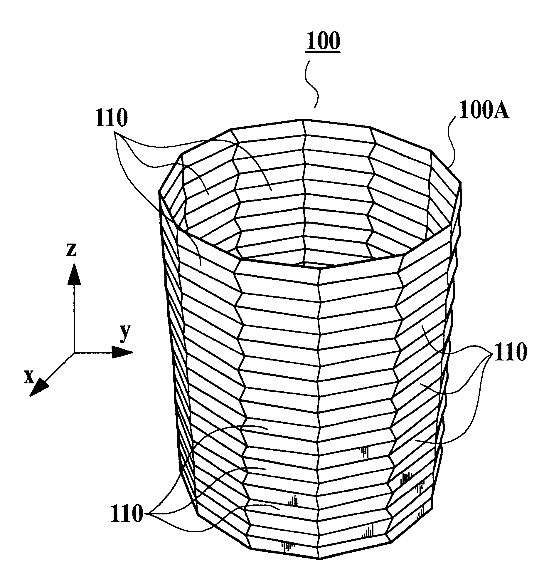
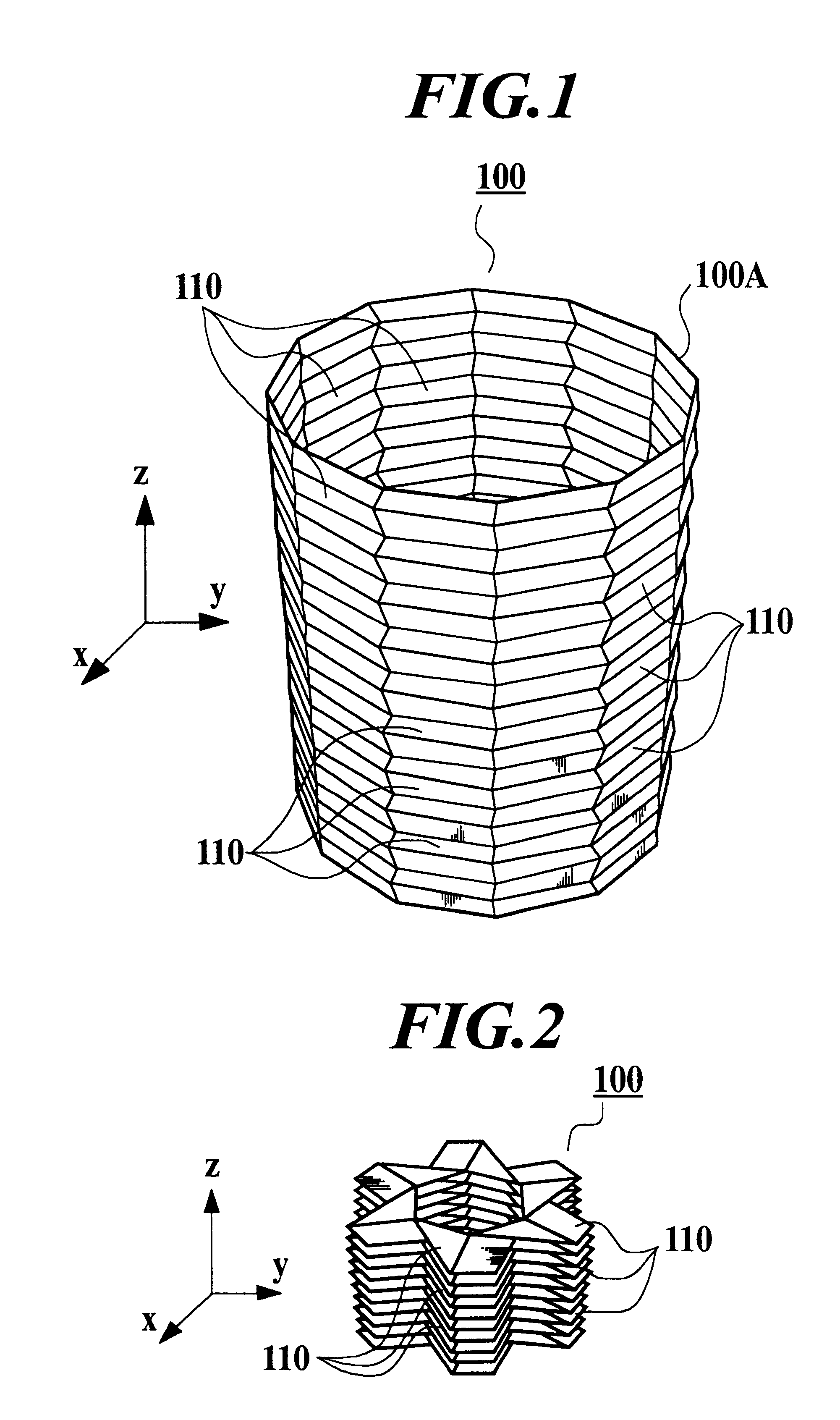
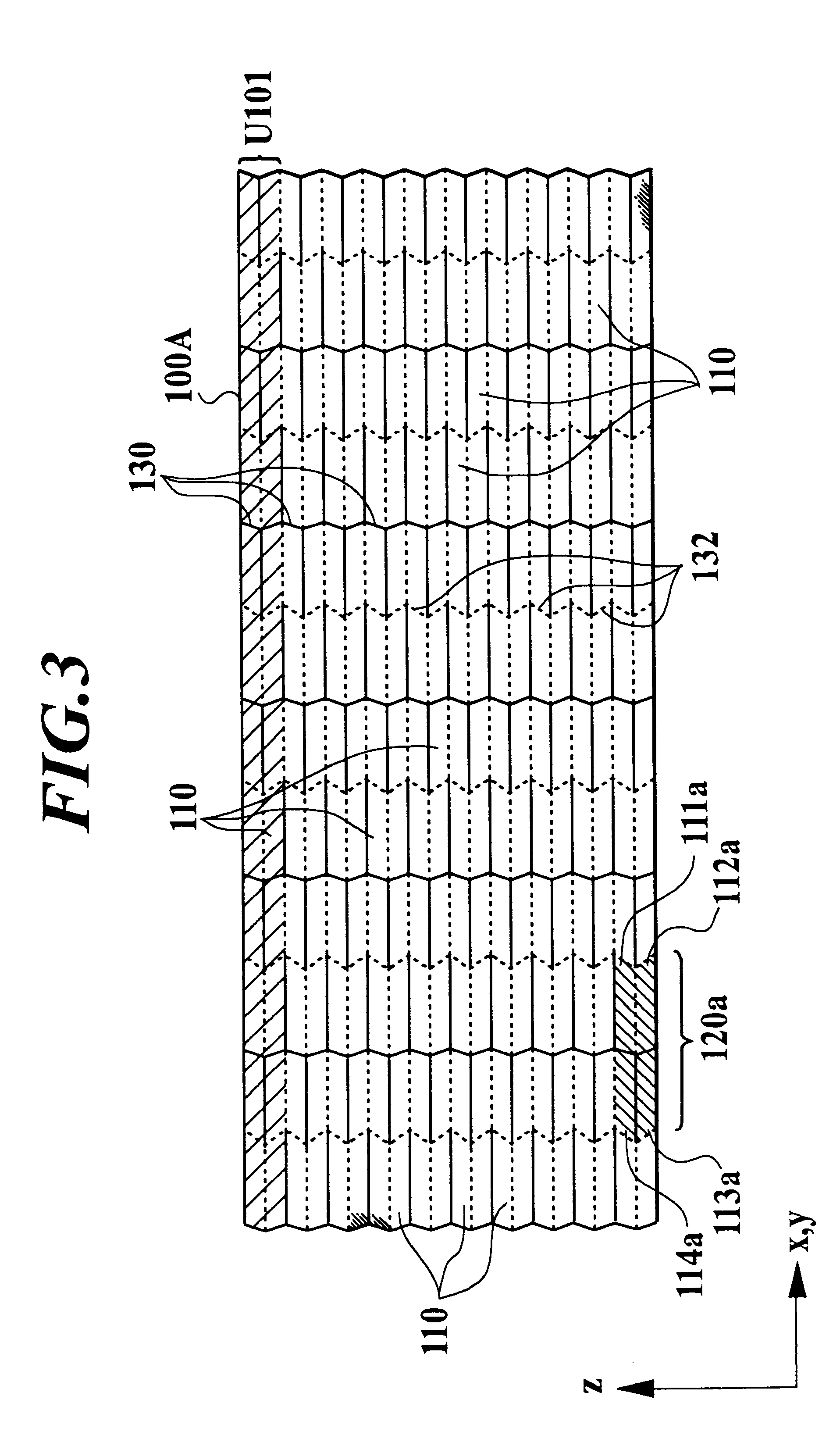
The tube-like deployable structure 100 comprises a plurality of ring-shaped units which are successively connected one after another in a Z-axial direction. Reference numeral U101 denotes one unit. The Z-axial direction means a direction of the central axis of the ring, as shown in FIG. 1. Each unit comprises six modules which are connected in a circumferential direction which is parallel with a X-Y-plane, as shown in FIG. 1. The X-Y-plane is perpendicular to the Z-axis. The module 120a comprises four segments 111a, 112a, 113a, and 114a each of which has the shape of a quadrangle, and which are connected to one another through connecting creases 120ao, 120ap, 120aq, and 120ar. Each adjacent segment, has an approximately same length relative to each other in the circumferential direction. The four segments 111a, 112a, 113a, and 114a are arranged to form a matrix of 2.times.2 so that the four connecting creases 120ao, 120ap, 120aq, and 120ar intersect at one point, as shown in FIGS. ...

second embodiment

A deployable structure according to the invention will be explained with reference to FIGS. 7 to 10, as follows.

FIG. 7 is a perspective view of a tube-like deployable structure 200 in a development state according to the second embodiment of the present invention, FIG. 8 is a perspective view of the tube-like deployable structure 200 in a packaged state, FIG. 9 is a plan development of the tube-like deployable structure 200, for explaining folds (creases) formed on the wall thereof, and FIG. 10 is a top view of the tube-like deployable structure 200 in a most packaged state. Dotted lines, which are parallel with the Z-axis, show the opening patterns in the connecting portions, while solid lines, which are parallel with the Z-axis, show the closing patterns in the connecting portions, as shown in FIG. 9. The opening patterns alternates with the closing patterns, in parallel with the Z-axis. The folding state in FIG. 10 is an ideal state and does not take into account a function of ov...

third embodiment

Next, a deployable structure according to the invention will be explained with reference to FIG. 19, as follows.

The tube-like deployable structure can be applied as a dust shield which protects the space systems from space debris and meteoroids. FIG. 19 is a schematic illustration of the tube-like deployable structure according to the third embodiment of the invention. Reference numeral 700 denotes the tube-like deployable structure, reference numeral 701 denotes a space shuttle, and reference numeral 702 denotes the space systems which is required to be protected from space debris or the like.

When the tube-like deployable structure 700, which is the axially symmetric type and the maximum number d.sub.max of the overlapped segments is four for one unit, is applied as the dust shield, the geometrical parameters are determined the by equations [Math 1] and [Math 2]. When a diameter 2R in the developed state is assumed to be 6 meters, a length in the direction of the central axis in th...


PUM


Abstract

A deployable structure comprising a side wall having a plurality of segments which make the side wall a tube-like shape as a whole. Four adjacent segments are connected with one another at one point to make one module. The folding patterns of the segments along the connecting creases have two purposes, one of which is a closing pattern to reduce an inner angle between connected segments adjacent in a circumferential direction of the side wall, accompanied with a folding in a direction of a central axis, the other of which is an opening pattern to enlarge the inner angle between connected segments adjacent in the circumferential direction of the side wall, accompanied with a folding in the direction of the central axis. As a result the side wall can be deployed and packaged in both directions of the central axis and the radius of the side wall by folding the segments along the connecting creases thereof in the closing and opening patterns.

Description

1. Field of the InventionThe present invention relates to a deployable structure which is tube-like to have a closed area, for example, in space, on the surface of the moon, on the earth, or the like.2. Description of Related ArtA tube-like structure having a side wall to create a closed area in space, as on the surface of the moon, the earth, or the like has been known. It is required that such a tube-like structure be deployable and packagable, for example, in point of transportation or the like. Some tube-like deployable structures have been proposed to satisfy the requirements above-described, in earlier technology. For example, a tube-like structure, the side wall of which enables deployment and packaging in a longitudinal direction, i.e., in a direction of a center axis of the tube-like structure, has been known.However, the earlier tube-like structures enable deployment and packaging only in the longitudinal direction. That is, the earlier tube-like structure is not deployabl...

Claims


Application Information

Patent Timeline
Patent Type & Authority Patents(United States)
IPC IPC(8): B64G9/00E04B1/343B64G99/00
CPCB64G9/00E04B1/34378B64G99/00E04B1/3449
Inventor SOGAME, AKITOSAITO, JUN
Owner NISHIMATSU CONSTR
Why Eureka
Try Eureka