Integrated well drilling and evaluation

a well and integrated technology, applied in the direction of wellbore/well accessories, survey, chemistry apparatus and processes, etc., can solve the problems of not being able to conduct conventional unable to complete draw-down and build-up tests, and being considered undesirable to flow test an open hol

Inactive Publication Date: 2001-05-22
HALLIBURTON ENERGY SERVICES INC
View PDF14 Cites 86 Cited by
  • Summary
  • Abstract
  • Description
  • Claims
  • Application Information

AI Technical Summary

Problems solved by technology

Such draw-down and build-up tests may take many days to complete.
While techniques and systems have been developed for testing open, uncased well bores, it is often considered undesirable to flow test an open hole well through a drill stem test string from the standpoint of safety considerations.
That is, the conduct of conventional draw-down and build-up testing in an open hole situation is dangerous in that the drill pipe is full of drilling mud which must be circulated out and it is possible for problems to occur such as blow-outs or differential pressure sticking of the pipe.
This, of course, involves the time and cost of pulling and running pipe and is disadvantageous from that standpoint.

Method used


Image

  • Integrated well drilling and evaluation
  • Integrated well drilling and evaluation
  • Integrated well drilling and evaluation

Examples


Embodiment Construction

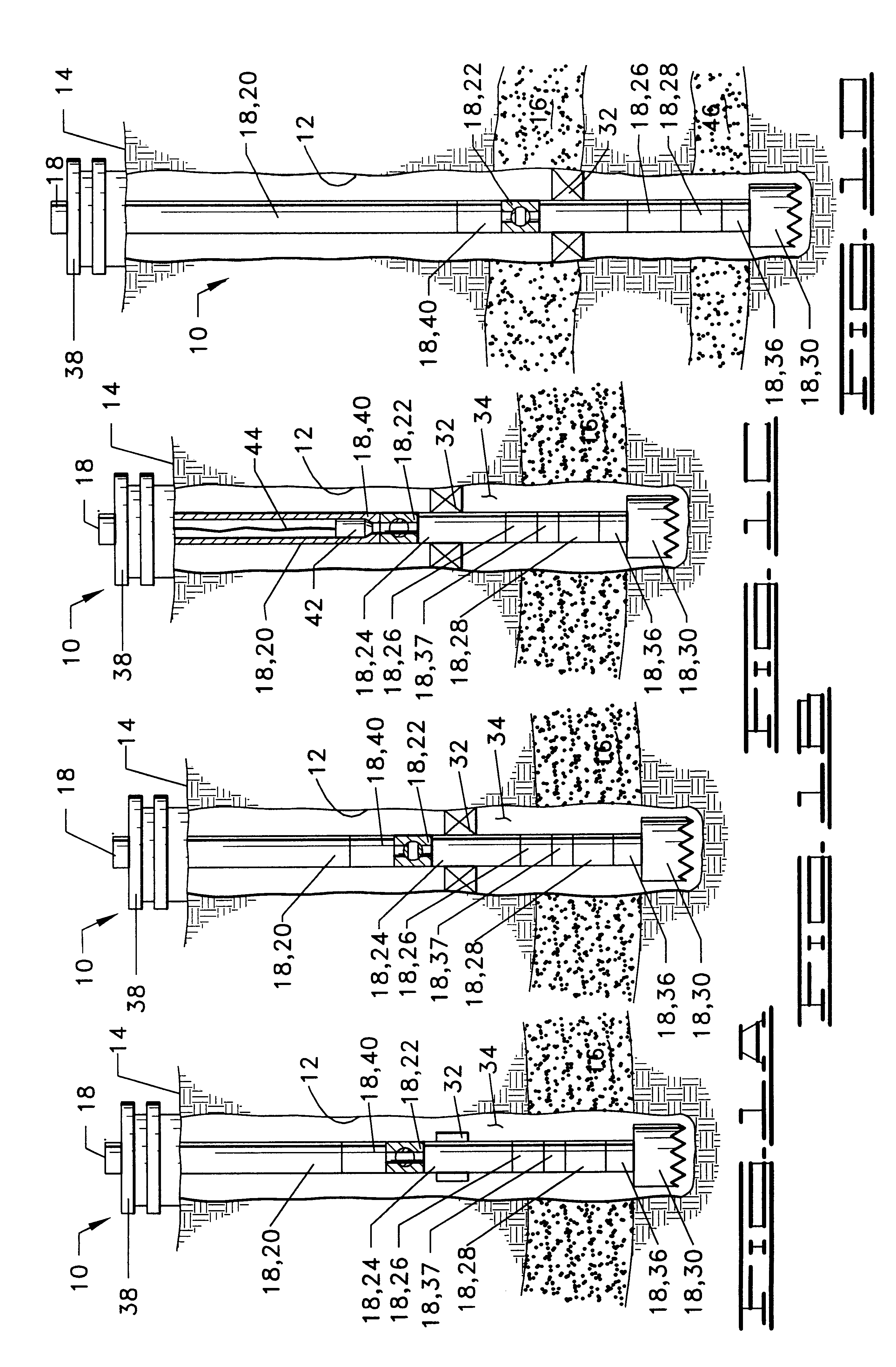
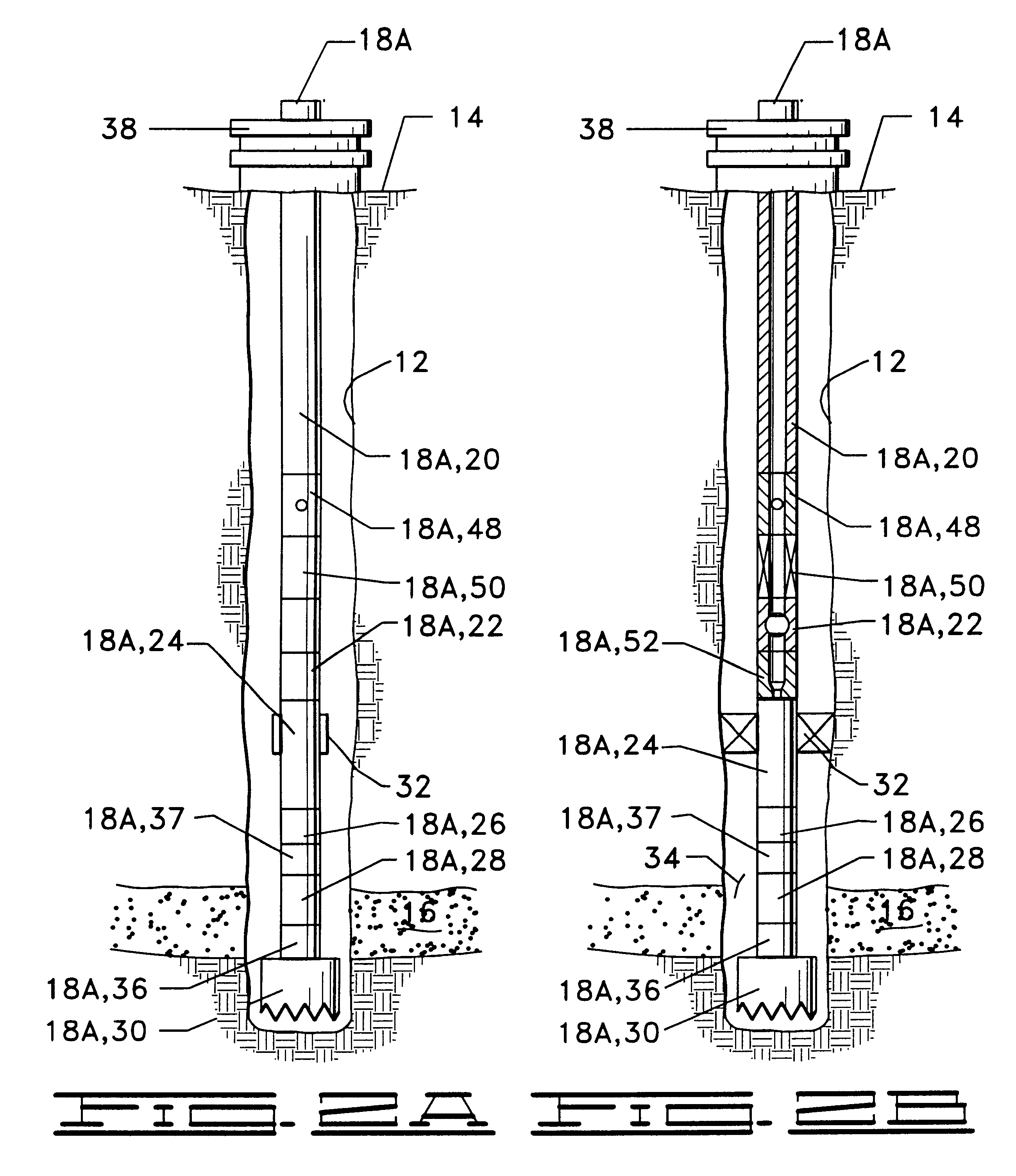
Referring now to the drawings, and particularly to FIGS. 1A-1D, the apparatus and methods of the present invention are schematically illustrated.

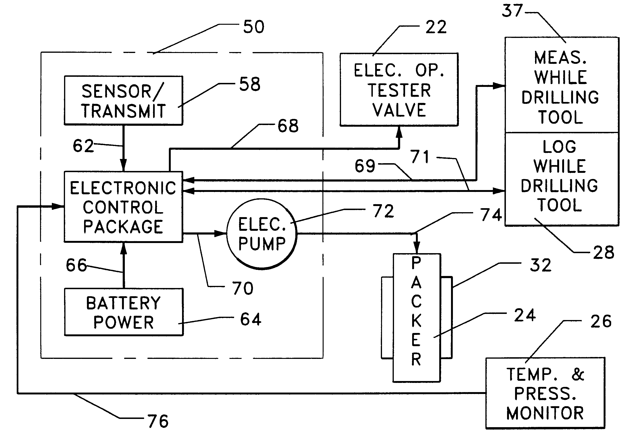
A well 10 is defined by a well bore 12 extending downwardly from the earth's surface 14 and intersecting a first subsurface zone or formation of interest 16. A drill string 18 is shown in place within the well bore 12. The drill string 18 basically includes a coiled tubing or drill pipe string 20, a tester valve 22, packer means 24, a well fluid condition monitoring means 26, a logging while drilling means 28 and a drill bit 30.

The tester valve 22 may be generally referred to as a tubing string closure means for closing the interior of drill string 18 and thereby shutting in the subsurface zone or formation 16.

The tester valve 22 may, for example, be a ball-type tester valve as is illustrated in the drawings. However, a variety of other types of closure devices may be utilized for opening and closing the interior of drill string 18. One suc...


PUM


Abstract

Integrated drilling and evaluation systems and methods for drilling, logging and testing wells are provided. The drilling and evaluation systems are basically comprised of a drill string, a drill bit carried on a lower end of the drill string for drilling a well bore, logging while drilling means included in the drill string for identifying subsurface zones or formations of interest, packer means carried on the drill string above the drill bit for sealing a zone or formation of interest below the packer means, and a fluid testing means included in the drill string for controlling the flow of well fluid from the zone or formation of interest into the drill string. The drilling and evaluation systems and methods for using the systems allow one or more subsurface zones or formations of interest in a well to be drilled, logged and tested without the necessity of removing the drill string from the well.

Description

1. Field of the InventionThe present invention relates generally to the drilling of oil and gas wells, and more particularly, to systems and methods for drilling well bores and evaluating subsurface zones of interest as the well bores are drilled into such zones.2. Description of the Prior ArtDuring the drilling and completion of an oil and / or gas well, it is usually necessary to test and evaluate the production capabilities of the well. This is typically done by isolating a subsurface zone or formation of interest therein which is to be tested and subsequently flowing well fluid either into a sample chamber or up through a tubing string to the surface. Various data such as pressure and temperature of the produced well fluids may be monitored downhole to evaluate the long term production characteristics of the zone or formation.One very commonly used well testing procedure is to first cement a casing in the well bore and then to perforate the casing adjacent one or more zones of int...

Claims


Application Information

Patent Timeline
Patent Type & Authority Patents(United States)
IPC IPC(8): E21B49/00E21B33/127E21B33/12E21B49/08E21B47/00E21B47/06
CPCE21B33/1272E21B33/1275E21B47/00E21B47/06E21B49/00E21B49/081E21B49/088
Inventor SCHULTZ, ROGER L.BECK, H. KENTRINGGENBERG, PAUL D.CLARK, J. ALLANMANKE, KEVIN R.
Owner HALLIBURTON ENERGY SERVICES INC
Why Eureka
Try Eureka