Switch unit

a technology of switch unit and switch body, which is applied in the direction of switch details, switches with three operating positions, contact mechanisms, etc., can solve the problems of increasing the number of parts, restricting the design of door trims, and increasing the setting space of units

Inactive Publication Date: 2001-05-29
YAZAKI CORP
View PDF3 Cites 31 Cited by
  • Summary
  • Abstract
  • Description
  • Claims
  • Application Information

AI Technical Summary

Benefits of technology

And, when one end portion or the other end portion of the operative body is pushed toward the first or second contact portion, respectively, the operative body swings about the other end portion or one end portion, respectively, which can reduce upward projection of the other end portion or one end portion of the operative body.
Accordingly, distance between the decorative member and the base can be reduces, which attains thin-modeling of the switch unit itself, thereby reducing a mounting space thereof.
Since the elastically deforming portion returns the operative body to the original position when the pushing operation of the operative body ends, the number of parts can be reduced with its simple structure, thereby reducing the cost of the switch unit.
Further, when the operative body is swung, the operative body is operated, firstly, with relatively weak force till the fulcrum piece reaches the fulcrum receiving portion and, subsequently, with relatively strong force after the fulcrum piece has reached the fulcrum receiving portion. Therefore, the operative body can be operated with almost the same feeling as of the conventional one without giving a driver uncomfortable feeling.
According to the above-described structure, the elastic support member can protect the inside of the operative body and under the decorative member from a liquid such as water, whereby failure of the switch unit can be prevented.
According to the above-described structure, the elastic support member can be easily formed, whereby the cost of the switch unit can be further reduced.

Problems solved by technology

Consequently, the conventional switch unit has a relatively large thickness, which increases a setting space of the unit onto the door trim and restricts a design of the door trim.
Further, the conventional switch unit requires the pressing pin and the returning spring are necessary, which increases the number of parts, thereby lowering the efficiency of assembly work and raising the cost.

Method used


Image

  • Switch unit
  • Switch unit
  • Switch unit

Examples


Embodiment Construction

)

An embodiment of the present invention will now be described in further detail with reference to the accompanying drawings.

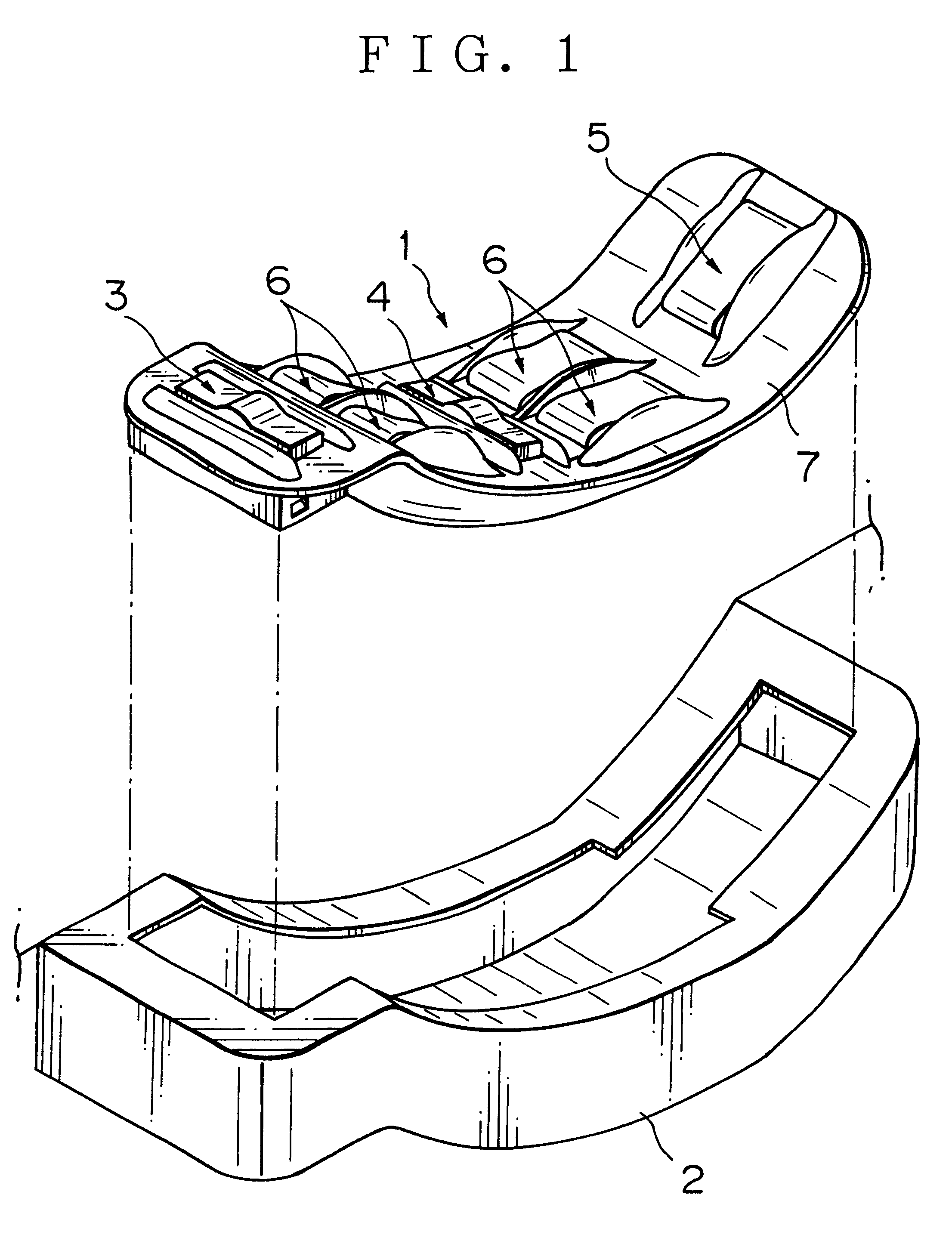
A switch unit 1 as an embodiment of the present invention is mounted onto an arm rest 2 provided on a driver's seat-side door trim of a vehicle, as shown in FIG. 1.

The switch unit 1 operates a powerwindow unit equipped on a vehicle. The powerwindow unit makes a window glass attached to the door trim go up and down. The switch unit 1 shown in FIG. 1 conducts a going up and down operation of all the window glasses of a vehicle.

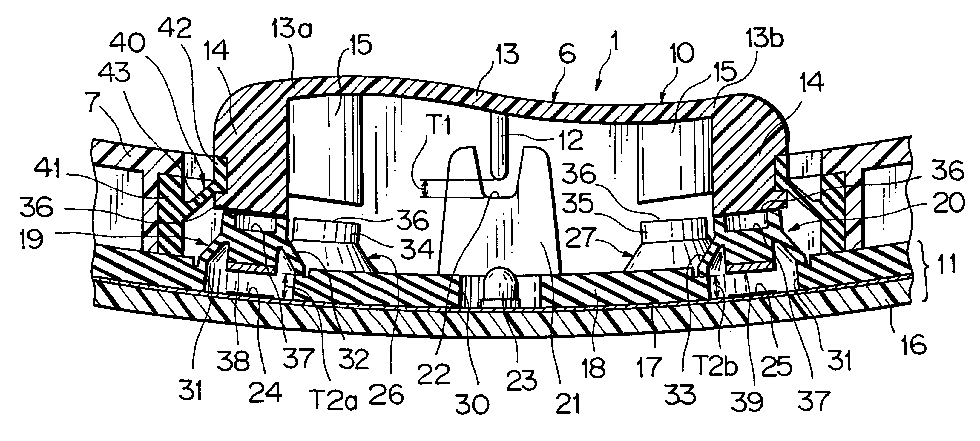
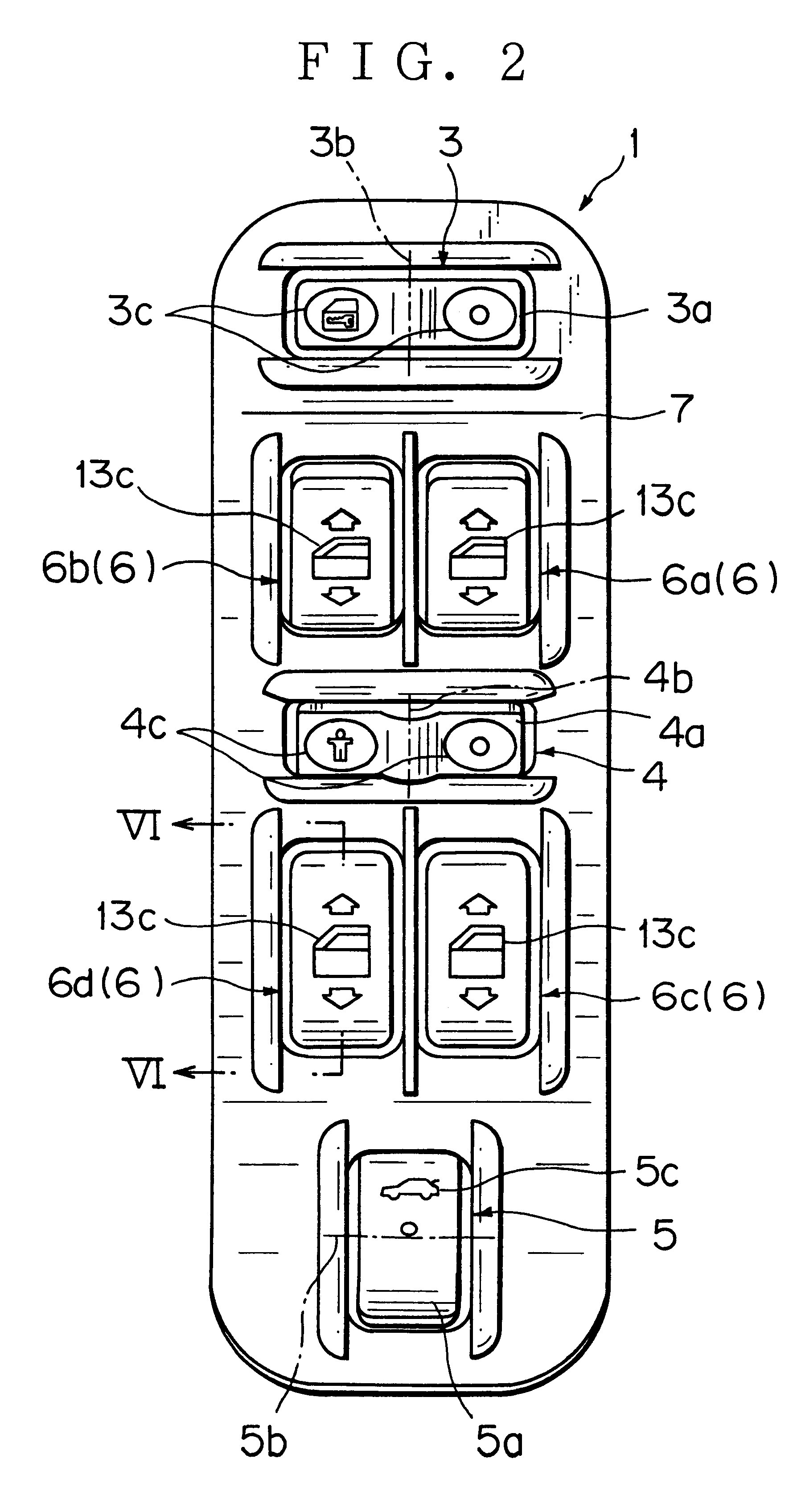
The switch unit 1, as shown in FIGS. 1 and 2, is equipped with a door locking switch 3, a window locking switch 4, a trunk opening switch 5, a plurality of window switches 6, and a decorative member 7 which exposes these switches 3,4,5,6 for a driver, covers various devices provided inside the switch unit 1, and prevents garbage from invading inside the switch unit 1.

The door locking switch 3 is arranged at the front among the switches 3,4,...


PUM


Abstract

A switch unit is provided, which includes: an operative body being swingingly operably provided; a first contact portion being abuttable on one end portion of the operative body when the operative body is swingingly operated; a second contact portion being abuttable on the other end portion of the operative body when the operative body is swingingly operated; a fulcrum piece extending from a middle portion of the operative body in a direction where the operative body comes into contact with and gets off the first and second contact portions; a fulcrum receiving portion facing the fulcrum piece; an elastic support member to support the operative body in a state that the fulcrum piece and the fulcrum receiving portion have a gap therebetween when the operative body is not operated and to permit the fulcrum piece to approach the fulcrum receiving portion when the operative body is operated.

Description

1. Field of the InventionThe present invention relates to a switch unit to be used for operating various devices such a powerwindow unit mounted on a vehicle such as a motor vehicle.2. Description of the Related ArtA powerwindow unit up / down-operates a window glass installed at a door trim of a vehicle. Based on an operation signal from a switch unit provided on the door trim, the powerwindow unit drives a motor and so on for up / down-operating the window glass, thereby open and close a window.The above switch unit has a knob as a operative body which is swingingly operably provided, a printed circuit board, a decorative members to cover the printed circuit board and to make the knob exposed. A first contacting member facing the printed circuit board is provided on one end portion of the knob. A second contacting member facing the printed circuit board is provided on the other end portion of the knob.Between the first contacting member and one end portion of the knob provided are a r...

Claims


Application Information

Patent Timeline
Patent Type & Authority Patents(United States)
IPC IPC(8): H01H23/00H01H23/02H01H23/30
CPCH01H23/003H01H23/025H01H2300/01
Inventor SERIZAWA, YASUYOSHIKUBOTA, MINORUNISHITANI, KEIZO
Owner YAZAKI CORP
Why Eureka
Try Eureka