Open-loop light intensity calibration systems and methods

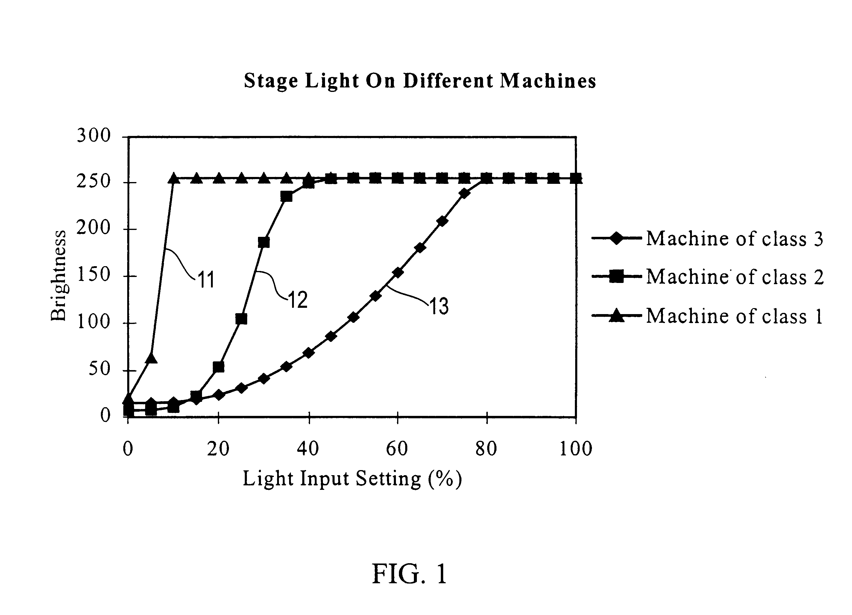
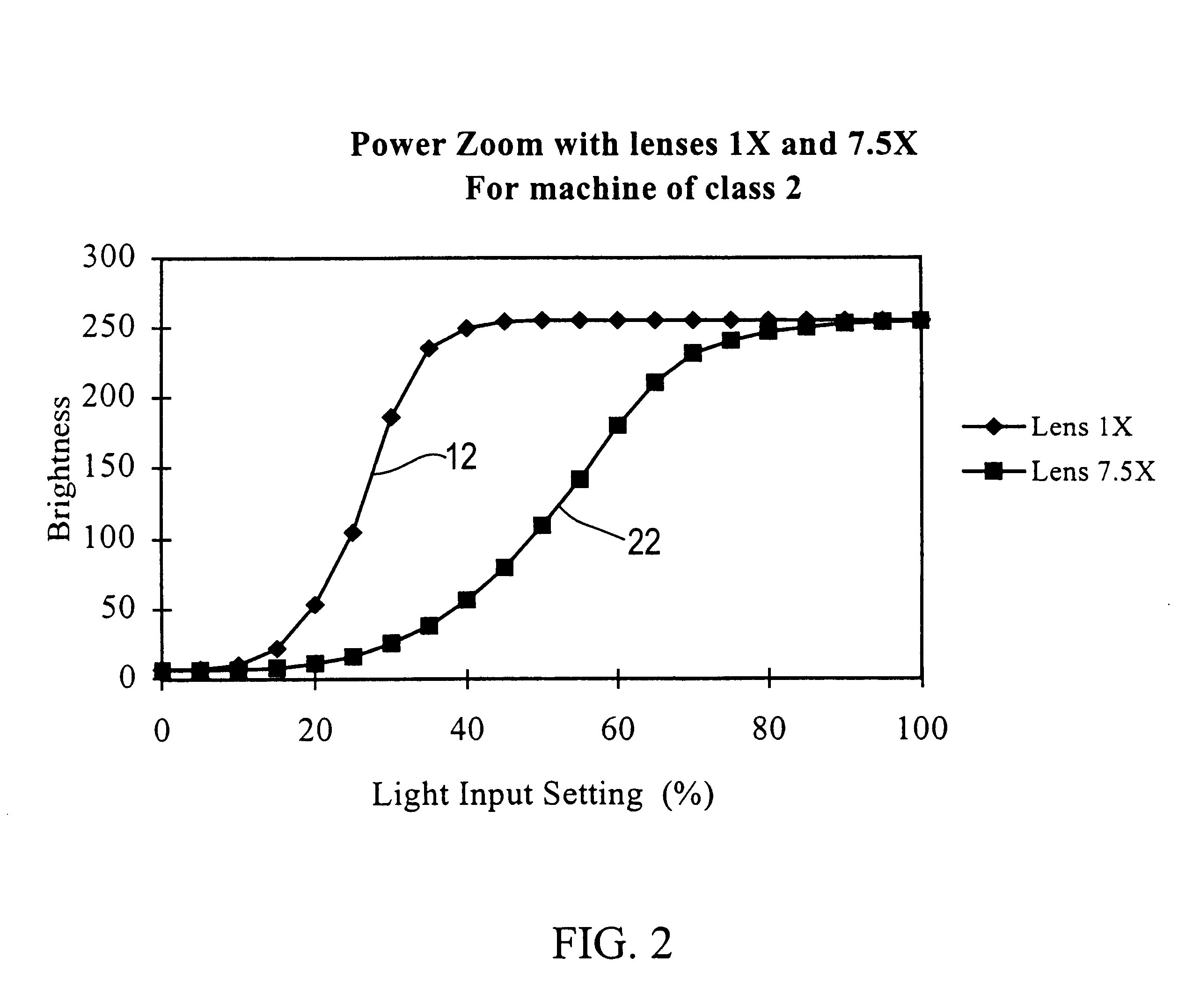
a technology of open-loop light intensity and calibration system, which is applied in the direction of process and machine control, optical radiation measurement, instruments, etc., can solve the problems of not being able to predict the same lighting behavior on different classes of vision systems, and it is difficult to interchange parts of even similar particular vision systems of the same class of vision systems

Inactive Publication Date: 2001-05-29
MITUTOYO CORP
View PDF8 Cites 37 Cited by
  • Summary
  • Abstract
  • Description
  • Claims
  • Application Information

AI Technical Summary

Problems solved by technology

Without adequate standardization and repeatability, archived programs vary in performance over time and within different instruments of the same model and equipment.
Moreover, the output light intensity can not be measured directly by the user.
By design, the same lighting behavior cannot be expected to occur on different classes of vision systems or on the same vision system when using different optical

Method used


Image

  • Open-loop light intensity calibration systems and methods
  • Open-loop light intensity calibration systems and methods
  • Open-loop light intensity calibration systems and methods

Examples


Embodiment Construction

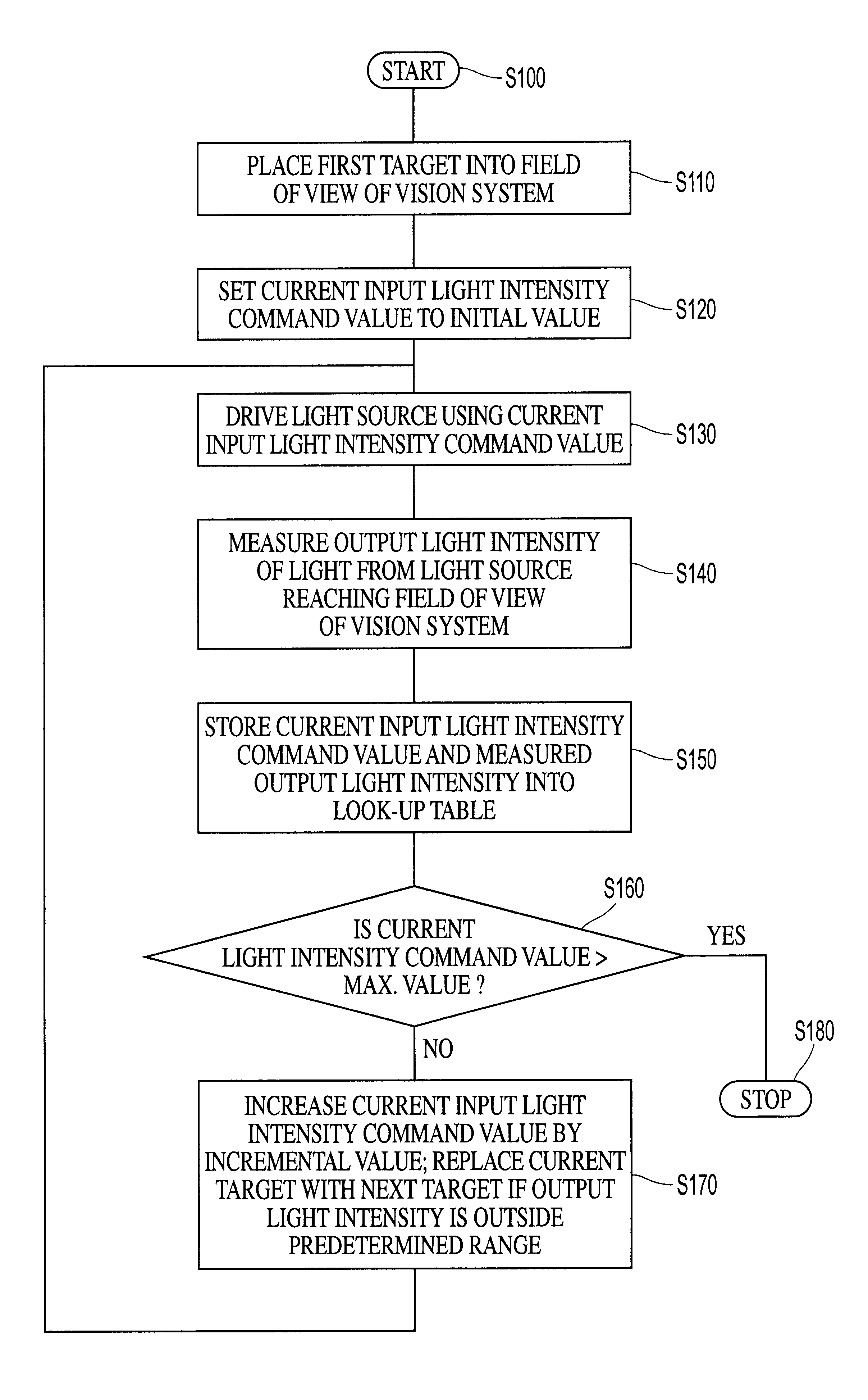
For simplicity and clarification, the operating principles, and design factors of this invention are explained with reference to one exemplary embodiment of a vision system according to this invention as shown in FIG. 4. The basic explanation of the operation of the vision system shown in FIG. 4 is applicable for the understanding and design of any vision system that incorporates the lighting calibration systems and methods according to this invention.

As used herein, the input light intensity command value "V.sub.i " is the light intensity value set by the user to control the light output intensity of the source light. The input light intensity command value is set either expressly in a part program or using a user interface. The range of the input light intensity command value is between zero and one, which represents a percentage of the maximum output intensity possible. In the following description, the ranges 0-1 and 0%-100% are used interchangeably. It should be appreciated tha...


PUM


Abstract

The input light settings in many vision systems often do not correspond to fixed output light intensities. The relationships between the measured output light intensity and the input light intensity are inconsistent between vision systems or within a single vision system over time. This inconsistency makes it difficult to interchange part-programs even between visions systems of one model of vision systems, because a part program with one set of light intensity values might produce images of varying brightness on another vision system. However, many measurements depend on the brightness of the image. To solve this problem, a reference lighting curve is generated for a reference vision system, relating an input light intensity value to a resulting output light intensity. A corresponding specific lighting curve is generated for a specific vision system that corresponds to the reference vision system. A calibration function is determined that converts a reference input light intensity value into a specific input light intensity value. Accordingly, when an input light intensity value is input, the specific vision system is driven at a corresponding specific input light intensity value such that the output light intensity of the specific vision system is essentially the same as the output light intensity of the reference vision system when the reference vision system is driven at the input light intensity value. Thus, in a vision system calibrated using these lighting calibration systems and methods, the specific lighting behavior of that vision system is modified to follow a pre-defined, or reference, lighting behavior.

Description

1. Field of the InventionThis invention relates to lighting systems for vision systems.2. Description of Related ArtThe light output of any device is a function of many variables. Some of the variables include the instantaneous drive current, the age of the device, the ambient temperature, whether there is any dirt or residue on the light source, the performance history of the device, etc. Machine vision instrument systems typically locate objects within their field of view using methods which may determine, among other things, the contrast within the region of interest where the objects may be found. To some degree, this determination is significantly affected by the amount of incident light or transmitted light.Automated video inspection metrology instruments generally have a programming capability that allows an event sequence to be defined by the user. This can be implemented either in a deliberate manner, such as programming, for example, or through a recording mode which progr...

Claims


Application Information

Patent Timeline
IPC IPC(8): G05D25/02G05D25/00G01J1/00G01J1/12G01J1/38
CPCG05D25/02H05B45/22
Inventor TESSADRO, ANA M.DEVORE, SCOTT L.
Owner MITUTOYO CORP
Why Eureka
Try Eureka