
Arrangement for firmly locking an engine bonnet to a vehicle cab

a technology for locking and engine, applied in the direction of locking applications, mechanical equipment, transportation and packaging, etc., can solve the problems of vibration propagation to the cab, large force, and large weight of the engine bonnet of a heavy-duty truck

Inactive Publication Date: 2001-06-05
SCANIA CV AB
View PDF9 Cites 17 Cited by
  • Summary
  • Abstract
  • Description
  • Claims
  • Application Information

AI Technical Summary

Benefits of technology

Making one part of a two-part locking arrangement resilient makes the movements of the bonnet more flexible. The resilient part absorbs the stresses which occur when the cab moves relative to the bonnet. This reduces the stresses in the bonnet and therefore reduces the risk of cracks in the bonnet. Vibrations are also reduced, which increases comfort in the cab.
Rattling in the locking arrangement is eliminated by one guide device being an integral part of one part of the locking arrangement and the other guide device being a washer provided with a thick rubber element. Driver comfort is improved.

Problems solved by technology

The bonnet of a heavy-duty truck is large and heavy and may weigh about 100 kg, which gives rise to large forces.
This produces stresses in the front edge of the bonnet which can gradually lead to cracks.
Another problem which arises when the cab springs vertically and the bonnet is thereby moved is that this causes vibrations which propagate to the cab.
This creates a considerable comfort problem for the driver, who often spends a large part of his working day in the cab.
A problem with these washers is that they may cause rattling in the locking arrangement.
This noise may be disturbing for the driver and thereby diminish comfort in the cab.

Method used


Image

  • Arrangement for firmly locking an engine bonnet to a vehicle cab
  • Arrangement for firmly locking an engine bonnet to a vehicle cab
  • Arrangement for firmly locking an engine bonnet to a vehicle cab

Examples


Embodiment Construction

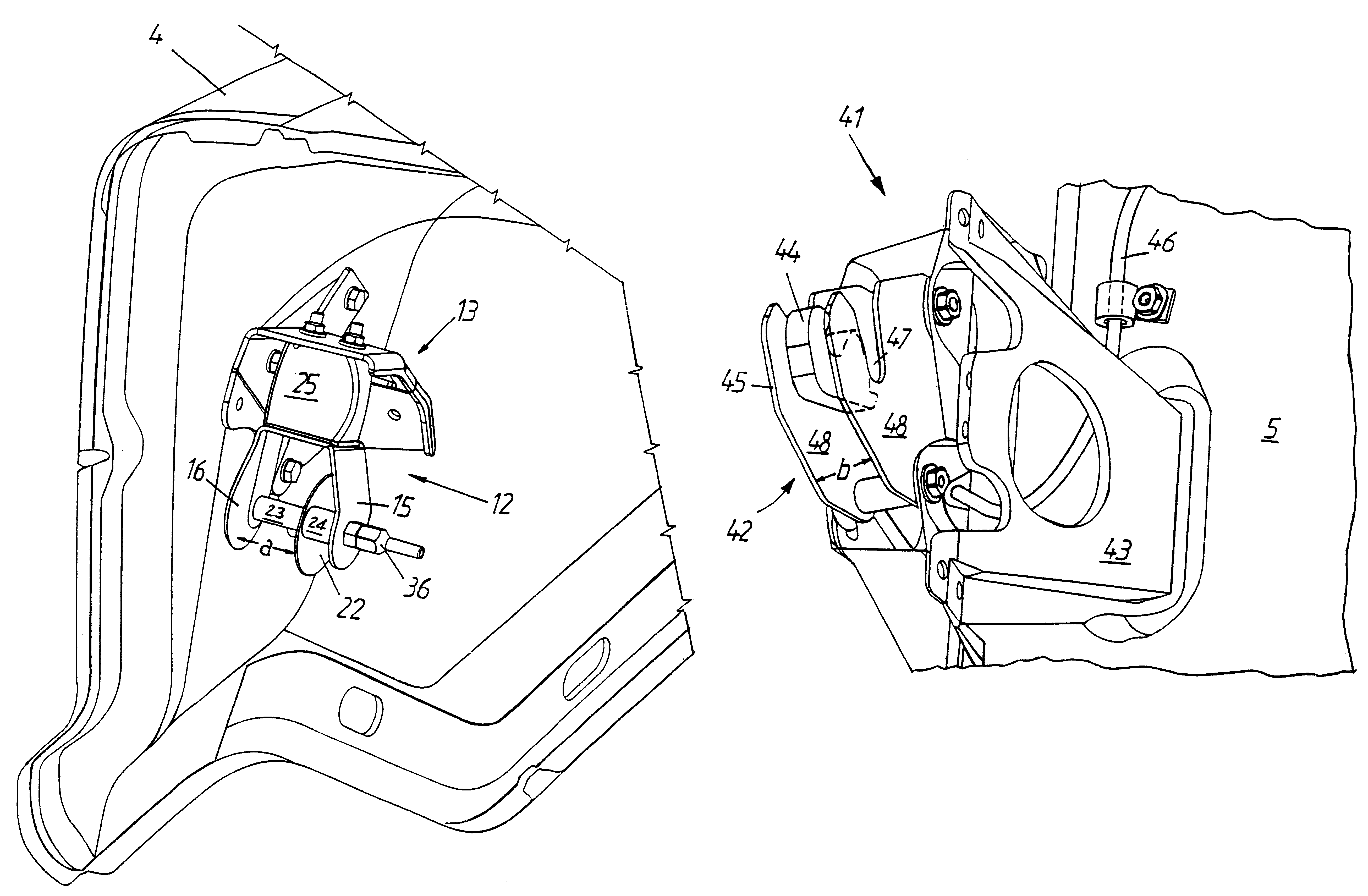
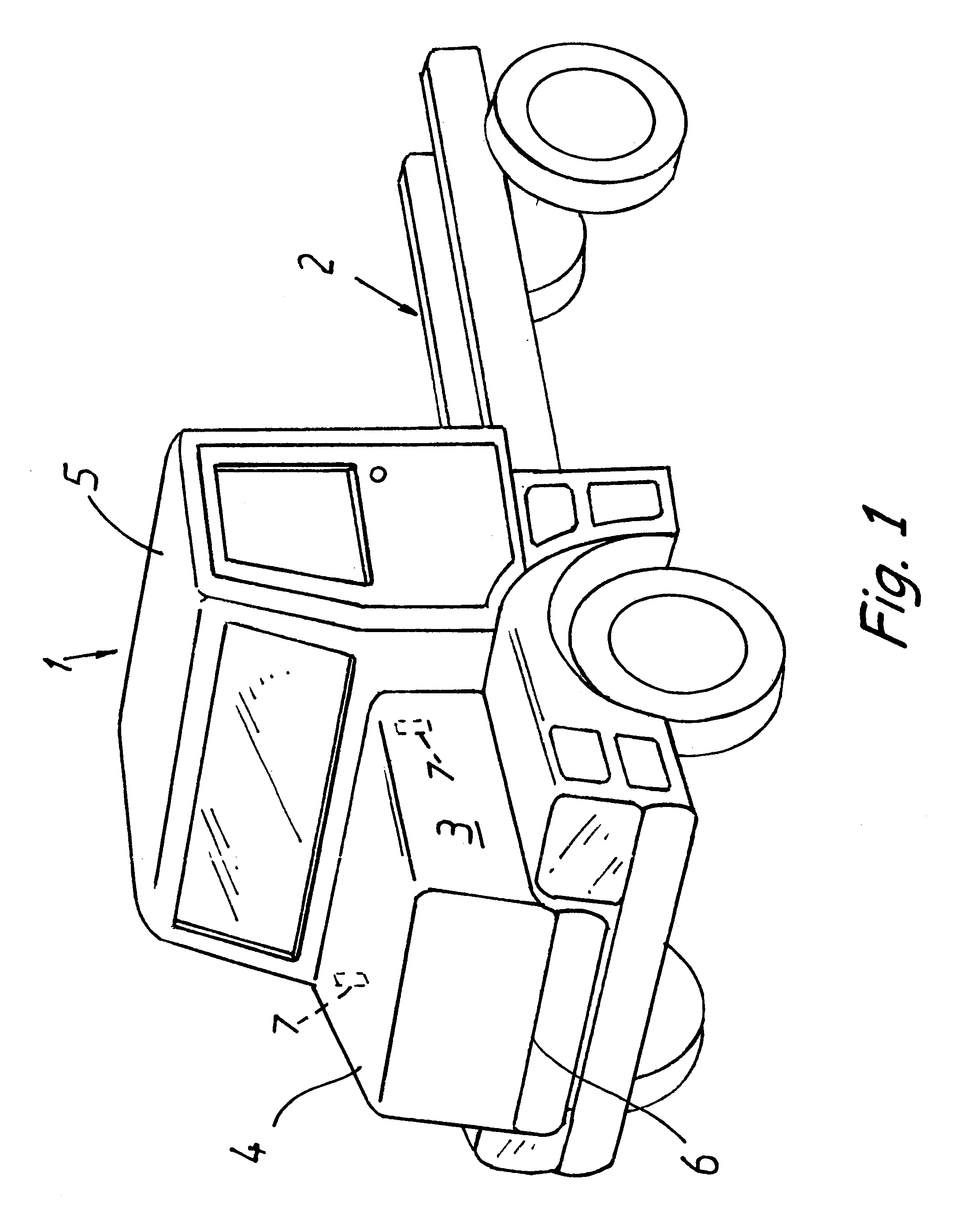
FIG. 1 depicts a so-called torpedo-style truck 1 which has its engine (not depicted) arranged on a vehicle frame 2 in an engine space 3. The engine space 3 is covered by an engine bonnet 4 which is tiltable forwards to provide access to items in the engine space 3 for servicing or other attention. A driving cab 5 is arranged on the vehicle frame 2 to the rear of the engine space 3 and the engine bonnet 4. The driving cab 5 may have its rear edge and its front edge, or only its rear edge, resiliently suspended on the frame.

The engine bonnet 4 is arranged for tilting relative to the frame 2 about a spindle extending substantially in the transverse direction of the vehicle and situated at the lower front edge 6 of the bonnet 4. The rear end of the bonnet 4 is locked to the cab 5 by two catches 7. Each catch 7 is comprised of a part fastened to the bonnet and a part fastened to the cab, which parts cooperate with one another. To allow tilting of the bonnet 3, the catches 7 may be opened...


PUM


Abstract

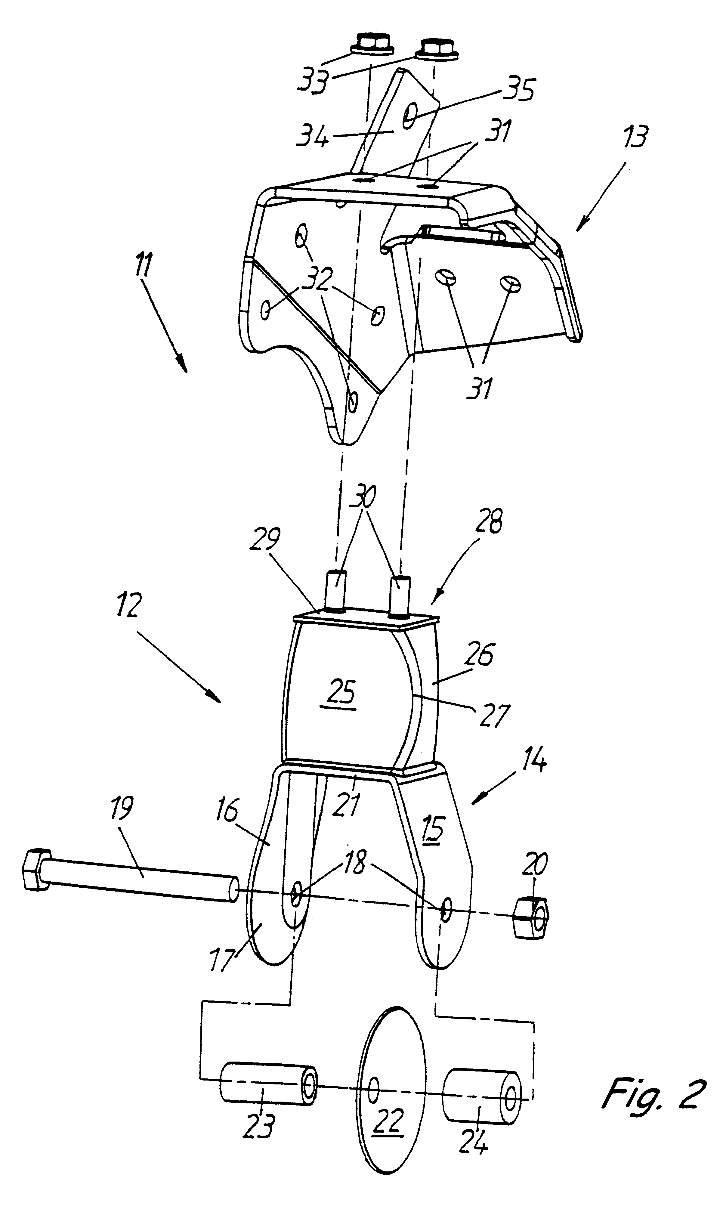
An arrangement for locking an engine bonnet firmly to a vehicle cab for reducing stresses on the bonnet and on the locking arrangement. The arrangement includes a first locking part fastened to the cab and a second locking part fastened to the bonnet. The first part includes a spindle supported between arms of a yoke. Facing convex dished guide surfaces at least one of which is resilient are disposed at the spindle. The receiving portion on the cab has two spaced apart plates each with a recess in it for receiving the spindle extending across them. The plates are placed so that the dished guide surfaces on the yoke of the receiving portion are engaged with the plates for guiding the spindle into the recess and for holding them against relative motion.

Description

The present invention relates to an arrangement for firmly locking an engine bonnet or hood to a vehicle cab and to the elements which guide the locking together and reduce the effects of relative motion between the bonnet and the cab.STATE OF THE ARTThere are at present two main types of heavy-duty trucks, the so-called cab-over-engine type, wherein the engine is largely arranged beneath a cab which is tiltable forwards, and the so-called torpedo type with its cab fastened to the frame and with the engine largely arranged in front of the cab in an engine space which is covered by an engine bonnet. The torpedo type has an engine bonnet with a front edge that is firmly arranged on the vehicle frame. The bonnet is often tiltable forwards about a transverse hinge pin which is arranged as far forward as possible on the vehicle at the lower front edge of the bonnet. The bonnet is locked firmly to the cab by a catch at the rear edge of the bonnet.Secure locking between the cab and the bon...

Claims


Application Information

Patent Timeline
IPC IPC(8): E05B15/02E05B65/12E05B15/00E05B65/19E05B17/00
CPCE05B15/022E05B83/16E05B77/42E05B85/045Y10T292/1047Y10T292/68
Inventor JARNSTROM, SUNEMALMQUIST, LEIF
Owner SCANIA CV AB
Learn More