
Interdigital slow-wave coplanar transmission line resonator and coupler

Inactive Publication Date: 2001-06-05
QORVO US INC
View PDF0 Cites 11 Cited by
  • Summary
  • Abstract
  • Description
  • Claims
  • Application Information

AI Technical Summary

Benefits of technology

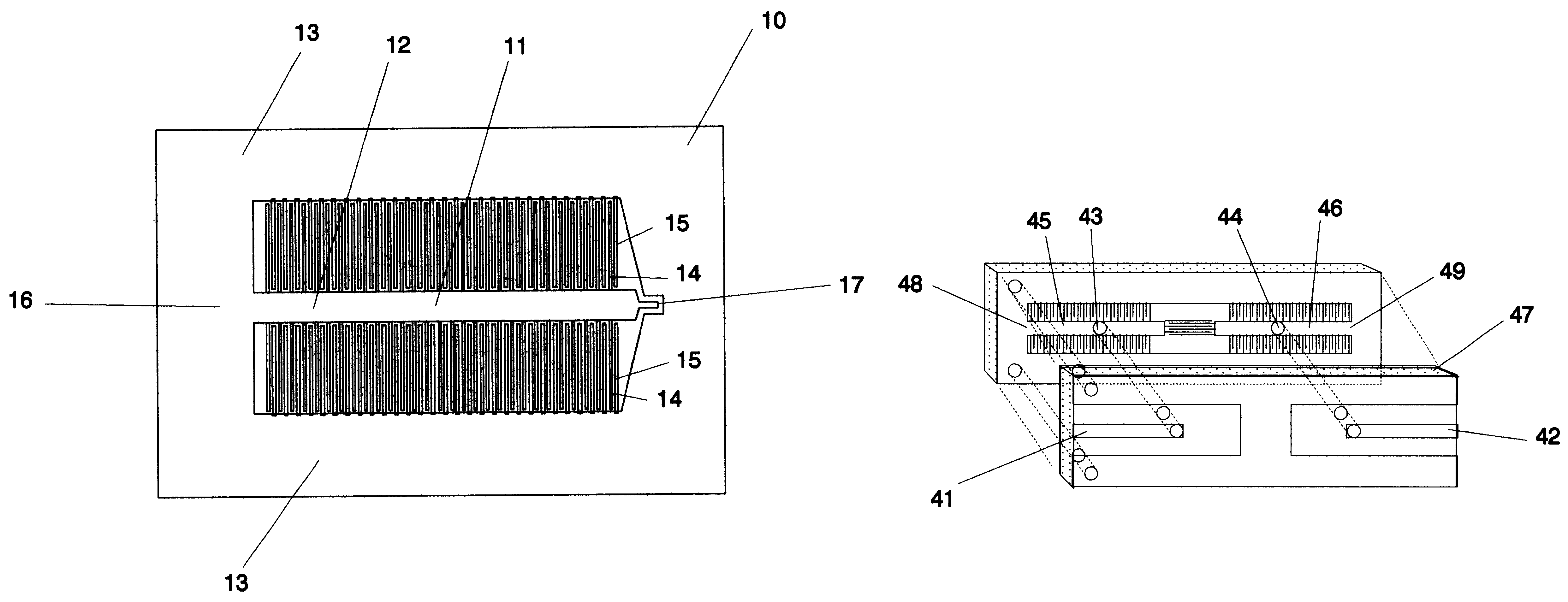
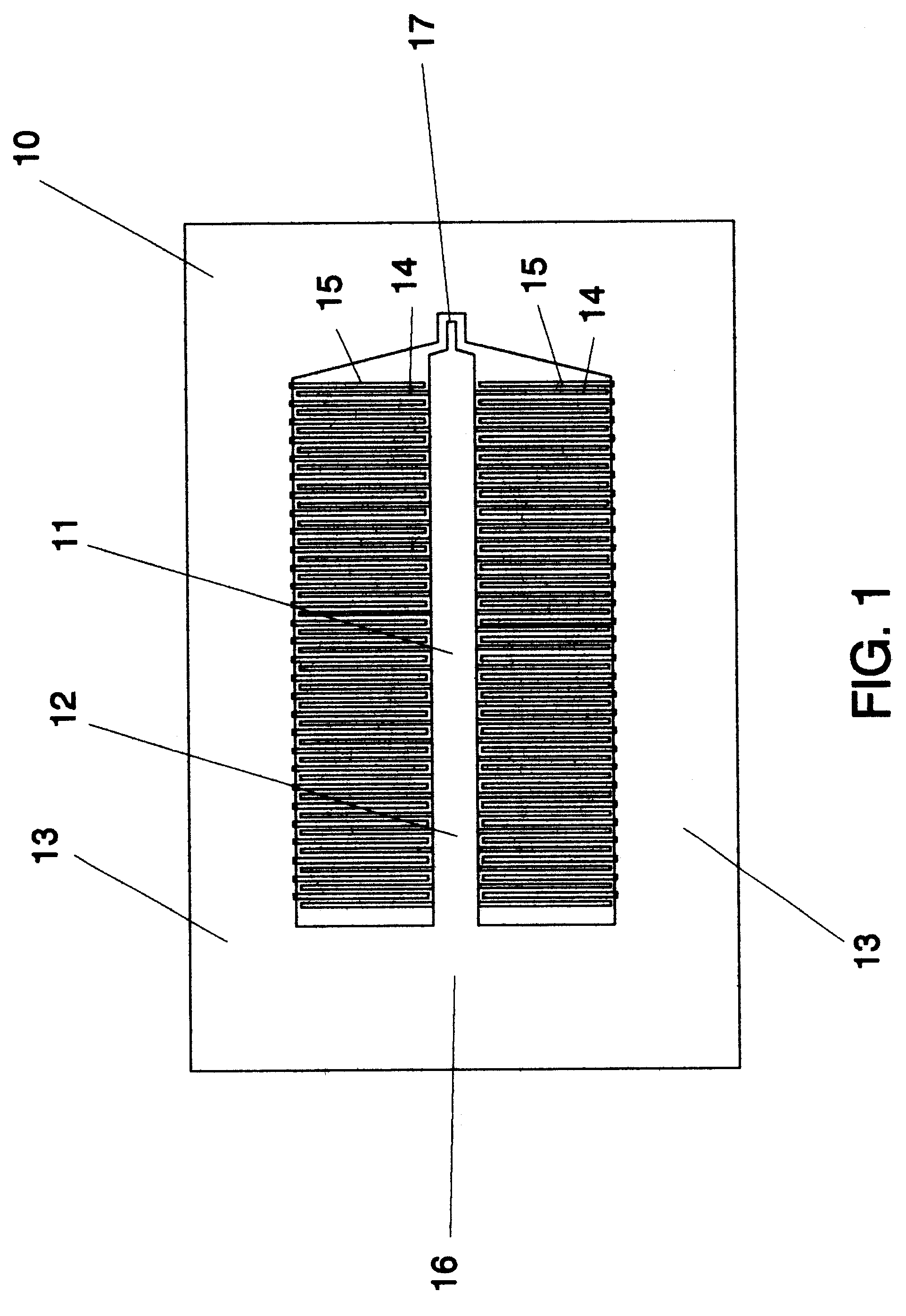
Instead of using an ordinary coplanar transmission line, the present invention uses a section of an interdigital slow-wave coplanar transmission line, such as that depicted in FIG. 1, that is short circuited to ground at one end of the transmission line to function as a resonator. The unexpected advantage of using an interdigital, slow-wave coplanar transmission line as a resonator is that, in contrast to using an ordinary co-planar transmission line, the frequencies at which the higher order modes begin to propagate along the interdigital, slow-wave transmission line are displaced much further from the frequencies at which the shorted, slow-wave transmission line is resonant. Because of the greater displacement, the interdigital, slow-wave coplanar transmission line can be used as a resonator for line lengths of odd integral multiples of a quarter-wave without being degraded by the propagation of higher order modes. Because the transmission line resonators that utilize line lengths that are higher odd-integral multiples of a quarter-wave, tend to exhibit a narrower bandwidth or higher Q resonance, such a multiple quarter wavelength resonator that utilizes an interdigital slow-wave coplanar transmission line provides better performance than a resonator that uses a multiple quarter wavelength of ordinary, coplanar transmission line.
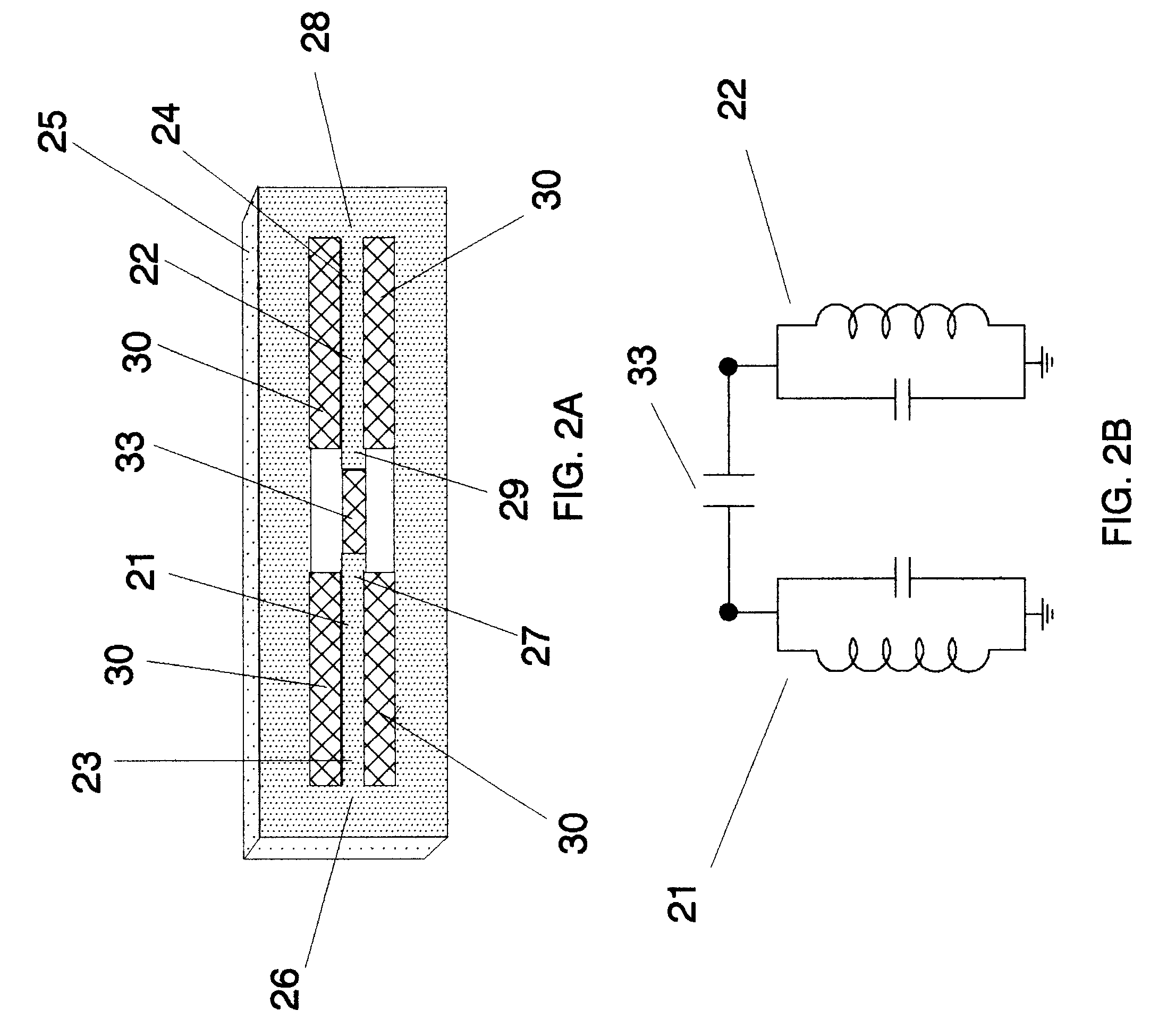
A second embodiment of invention includes a means for coupling to an interdigital, slow-wave, coplanar transmission line resonator that does not require the addition of wire tap or plated through holes in a substrate. This embodiment, instead, uses a portion of an ordinary coplanar transmission line that is electrically shorted at one end and that is overlaid in close proximity to the resonator, so as to couple the transmission line to the resonator. By using such coupling one avoids any need for wire taps and plated through holes as a means of electrically connecting to the resonator.

Problems solved by technology

An immediate practical problem associated with such a resonator is providing a means at microwave frequencies for connecting to the input port of the resonator.
However, in such a circumstance the Q of the resonator would be significantly depressed by the loading of the resonator by the impedance of the transmission line.

Method used


Image

  • Interdigital slow-wave coplanar transmission line resonator and coupler
  • Interdigital slow-wave coplanar transmission line resonator and coupler
  • Interdigital slow-wave coplanar transmission line resonator and coupler

Examples


Embodiment Construction

FIG. 1 depicts an interdigital, slow-wave coplanar transmission line resonator 10 located on the surface of a substrate. Transmission line 11 consists of central conductor 12 and ground conductors 13 that are symmetrically located on both sides of central conductor 12, all of which conductors are fabricated upon the surface of the substrate. Conducting fingers 14 extend from each side of central conductor 12 towards ground conductor 13 and are interleaved with conducting fingers 15 extending from ground conductor 13 towards central conductor 12. As described in the "532" patent, the capacitance between the interleaved fingers substantially slows the propagation of the TEM wave along the transmission line.

Central conductor 12 of transmission line 11 is electrically shorted to ground at shorted end 16. The opposite end of the transmission line serves as the input port 17 to the resonator. Input port 17 exhibits a high impedance at frequencies for which the length of transmission line ...


PUM


Abstract

A interdigital, slow-wave coplanar transmission line resonator utilizing a coupler. Sections of interdigital, slow-wave coplanar transmission lines having lengths of an integral number of quarter waves act as resonators. In one embodiment shorted transmission lines proximately located to the resonators electromagnetically coupled to the resonators to provide input and output ports to the resonators. In another embodiment, transmission lines are connected by taps to the resonators to provide input and output ports.

Description

1. BACKGROUND OF THE INVENTIONa. Field of the InventionThis invention pertains to resonators for use at microwave frequencies. More particularly, this invention pertains to the use of shorted, slow-wave coplanar transmission lines as microwave resonators or filters and devices for coupling to such resonators and filters.b. Description of the Prior ArtU.S. Pat. No. 5,777,532 ("532") discloses an interdigital, slow-wave coplanar transmission line consisting of two conducting strips that are located upon the surface of a substrate and that have interleaved conducting fingers that extend from the one side of each strip towards the opposite strip. The "532" patent also discloses a second, balanced configuration in which a central conducting strip is bounded on both sides by conducting grounds. Conducting fingers extend from the sides of the central conductor towards the grounds and interleave with conducting fingers extending from the grounds towards the central conductor. The capacitanc...

Claims


Application Information

Patent Timeline
IPC IPC(8): H01P7/08H01P3/00
CPCH01P3/003H01P7/086
Inventor LAKIN, KENNETH MEADE
Owner QORVO US INC
Learn More