Wireless rolling code security system

a security system and rolling code technology, applied in the field of security systems, can solve the problems of ineffective back-up or secondary sensors, several security risks of conventional security systems,

Inactive Publication Date: 2001-06-05
TSUI PHILIP Y W
View PDF8 Cites 109 Cited by
  • Summary
  • Abstract
  • Description
  • Claims
  • Application Information

AI Technical Summary

Problems solved by technology

Such conventional security systems provide several security risks.
Secondly, since all the peripheral devices operate using the same identif

Method used


Image

  • Wireless rolling code security system
  • Wireless rolling code security system
  • Wireless rolling code security system

Examples


Embodiment Construction

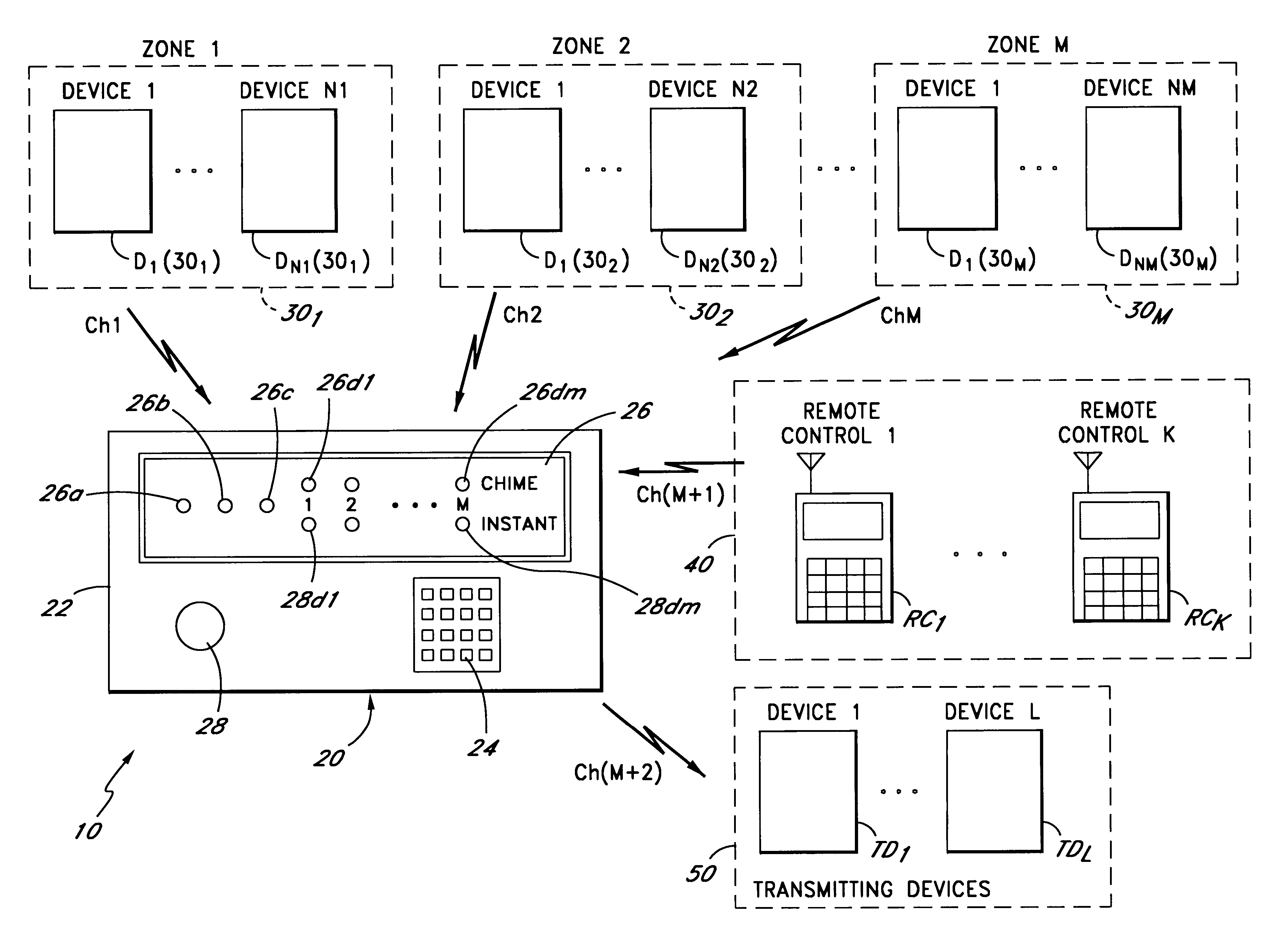
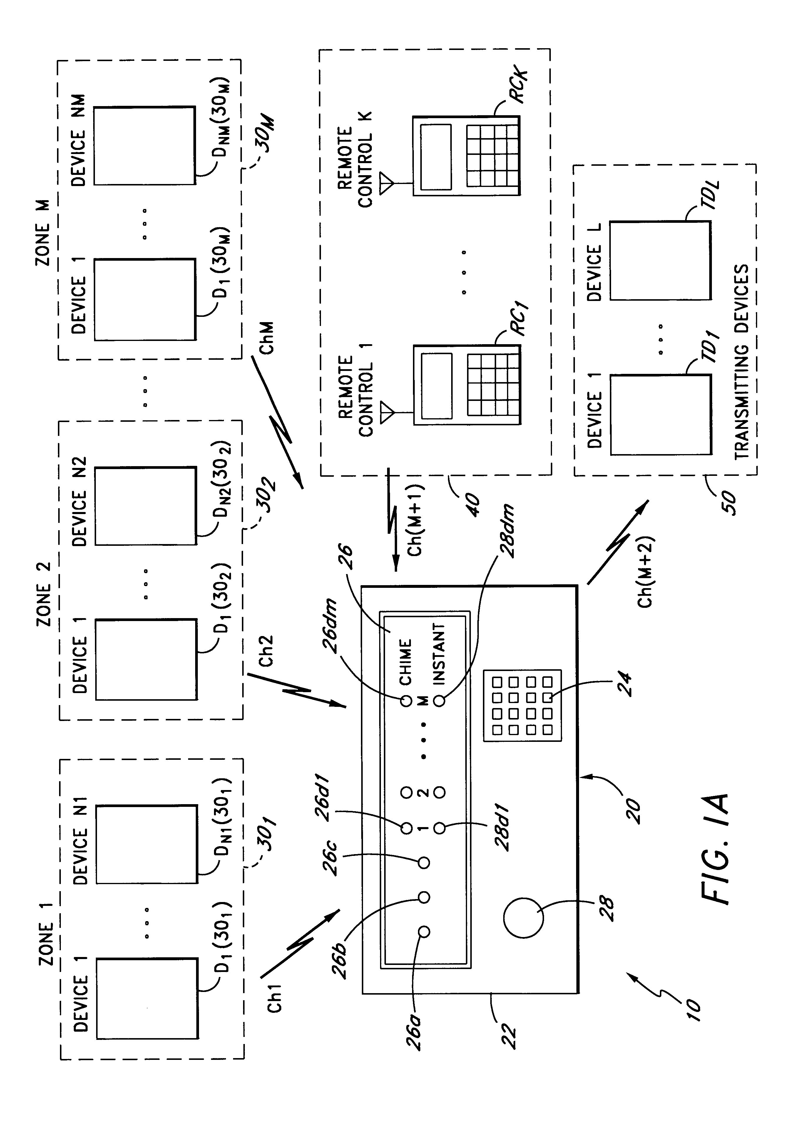
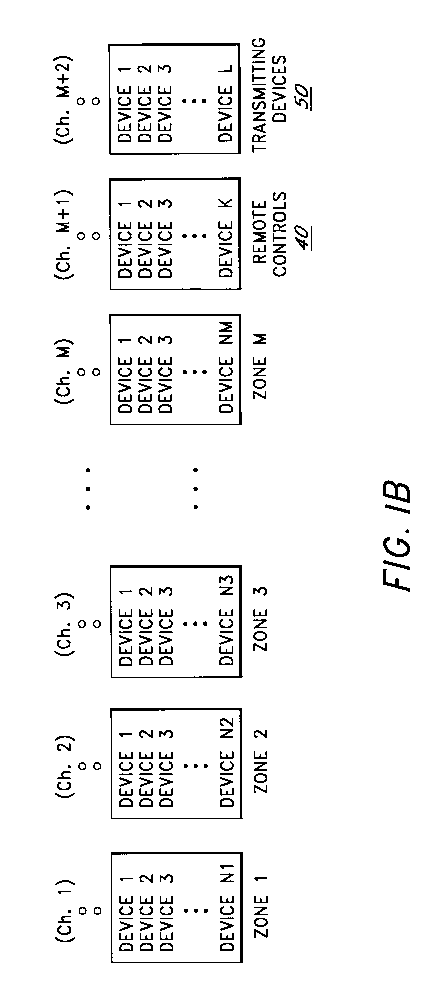
FIG. 1A is a block diagram illustrating one embodiment of the security system of the present invention. The security system 10 comprises a security console 20, a plurality of sets of peripheral devices D1(30.sub.1)-DN1(30.sub.1), D1(30.sub.2)-DN2(30.sub.2), . . . , D1(30.sub.M)-DNM(30.sub.M), each of which is allocated to a zone 30.sub.1, 30.sub.2, . . . , 30.sub.M respectively, a plurality of remote controllers RC1, . . . RCK (collectively referred to as remote controllers 40), and a plurality of transmitting devices TD1, . . . , TDL (collectively referred to as transmitting devices 50). In one embodiment, the number of peripheral devices D1(30.sub.1)-DN1(30.sub.1), D1(30.sub.2)-DN2(30.sub.2), . . . , D1(30.sub.M)-DNM(30.sub.M) are equal, i.e., N1=N2=NM. However, in alternate embodiments, any desired number of peripheral devices may be assigned to a particular zone 30.sub.1, 30.sub.2, . . . , 30.sub.M. Examples of the peripheral devices include sensors such as motion sensors, door / ...


PUM


Abstract

A processor-based transmitter-receiver system and method in which a receiver receives coded signals from at least two transmitters. A circuit for receiving a first coded signal from a first transmitter and a second coded signal from a second transmitter. Each of the coded signals includes a unique identification code and a variable security code. A memory stores at least two codes, each including a unique identification code and a variable security code. A processor coupled to the circuit and the memory, compares each of the received coded signals with each of the stored sets of codes. The processor generates a valid signal if one of the received coded signals matches one of the stored codes.

Description

1. Field of the InventionThis invention is directed in general to security systems and in particular, to a wireless security system in which a control unit which operates with a plurality of peripheral devices, is capable of receiving and verifying coded signals from each of the plurality of peripheral devices. The peripheral devices transmit the coded signals using a different data frame pattern during each transmission.2. Prior ArtTransmitter-receiver controller systems are widely used for remote control and / or actuation of devices or appliances such as garage door openers, gate openers, and security systems. For example, most conventional security systems use a transmitter-receiver combination to monitor selected areas. In such conventional security systems, all the peripheral devices such as sensors, and the control unit operate using the same identification code, so that only those devices belonging to a particular installed security system on the premises can operate with each...

Claims


Application Information

Patent Timeline
IPC IPC(8): G06F19/00G08B1/00H04B1/00
CPCG07C9/00182G07C2009/00253G08B25/008
Inventor TSUI, PHILIP Y. W.
Owner TSUI PHILIP Y W
Why Eureka
Try Eureka