Apparatus and method bonding optical fiber and/or device to external element using compliant material interface

a technology of material interface and apparatus, applied in the direction of optics, instruments, optical light guides, etc., can solve the problems of difficult automation of processes, poor yield of process, and insufficient protection of bonded optical fibers or devices according to these prior techniques

Inactive Publication Date: 2001-06-12
BLOOM CARY
View PDF101 Cites 16 Cited by
  • Summary
  • Abstract
  • Description
  • Claims
  • Application Information

AI Technical Summary

Problems solved by technology

However, the resulting bonded optical fiber(s) or device according to these prior techniques often times is not properly protected and/or affixed.
These processes are difficult to automate as well.
Thus, this process does not provide good yield results.
Further, these crude processes limit the types of optical devices

Method used


Image

  • Apparatus and method bonding optical fiber and/or device to external element using compliant material interface
  • Apparatus and method bonding optical fiber and/or device to external element using compliant material interface
  • Apparatus and method bonding optical fiber and/or device to external element using compliant material interface

Examples


first embodiment

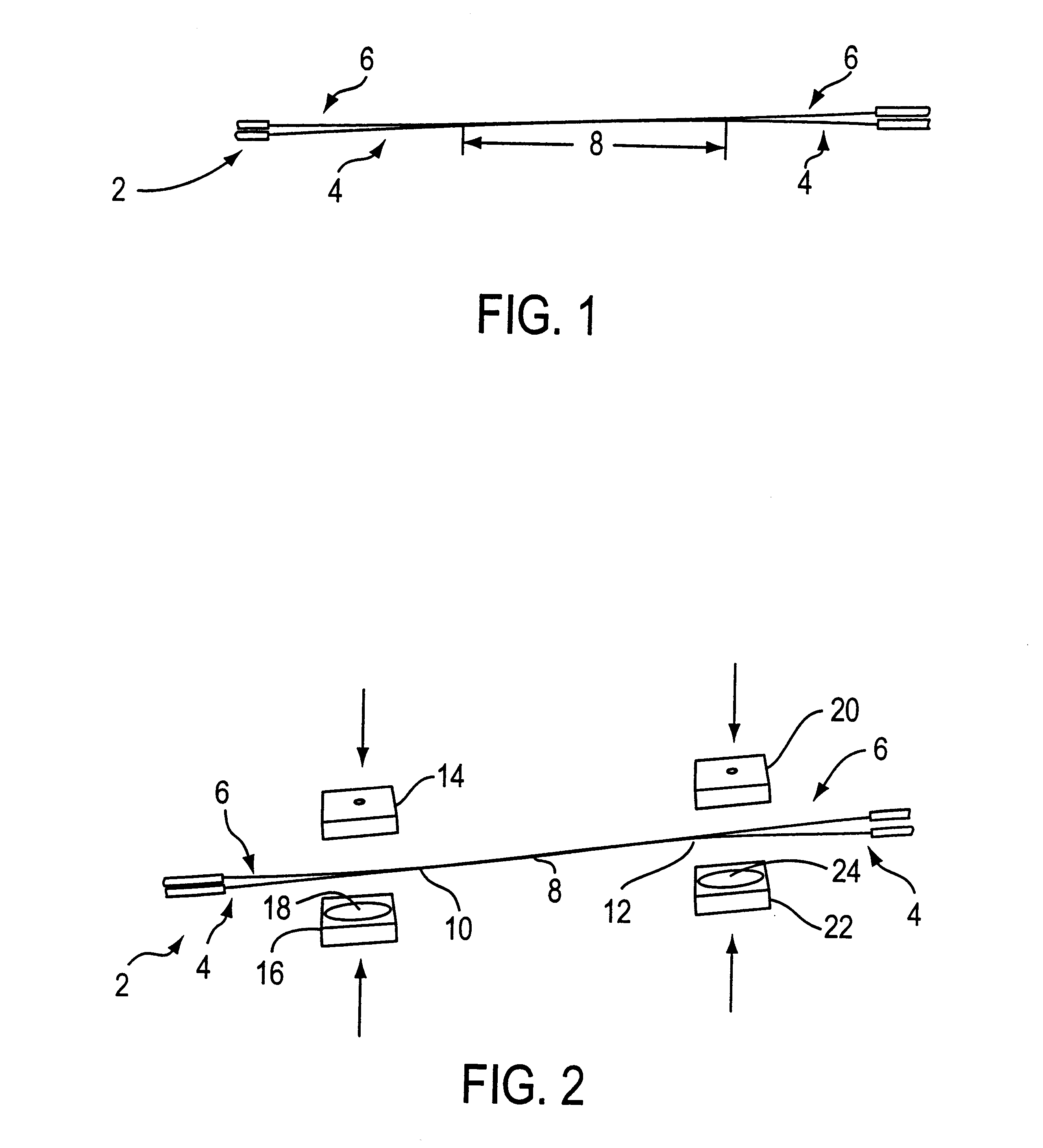
FIGS. 1-19 are illustrations of the process of the present invention according to the invention. FIG. 1 shows a fused-biconical tapered coupler 2 of two optical fibers 4, 6 that have been stripped of their coating in the fused region area 8. To properly package this device 2, the fused tapered region 8 must be secured, supported, and protected without any direct contact with the packaging.

FIG. 2 is the first step in this packaging procedure to create anchoring points at anchoring locations 10, 12 that will be used to secure the coupler 2 to the packaging. To allow a standard package size to be used, the anchor locations 10, 12 will generally be offset from the center of the device (e.g., fused region 8) by a standard distance. The offset distance is generally sufficient to place the anchoring locations 10, 12 close to, yet safely outside, the fused region 8. To create the anchor locations 10, 12, forms shown as blocks above (e.g., blocks 14, 20) and below (e.g., blocks 16, 22) the o...

second embodiment

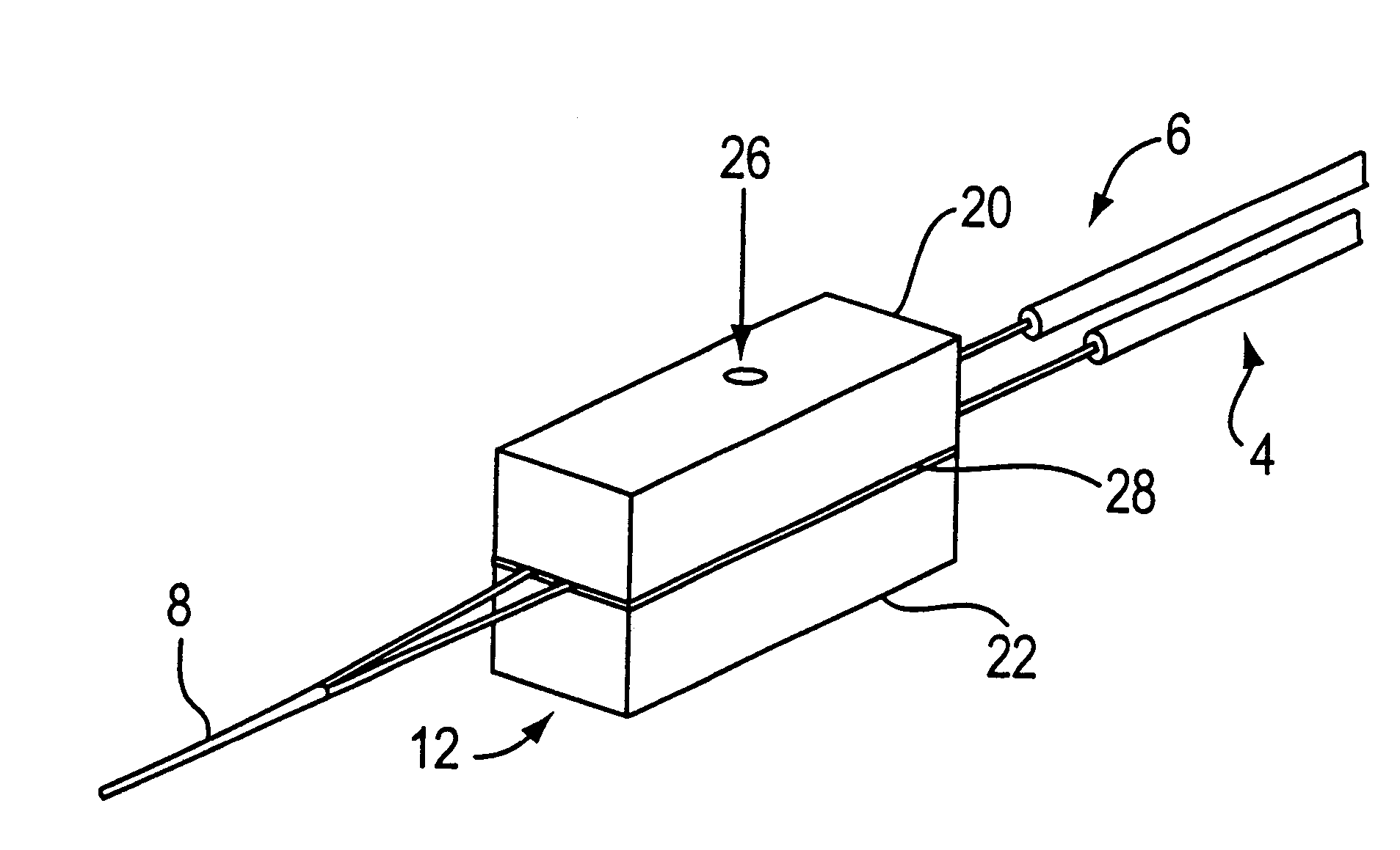
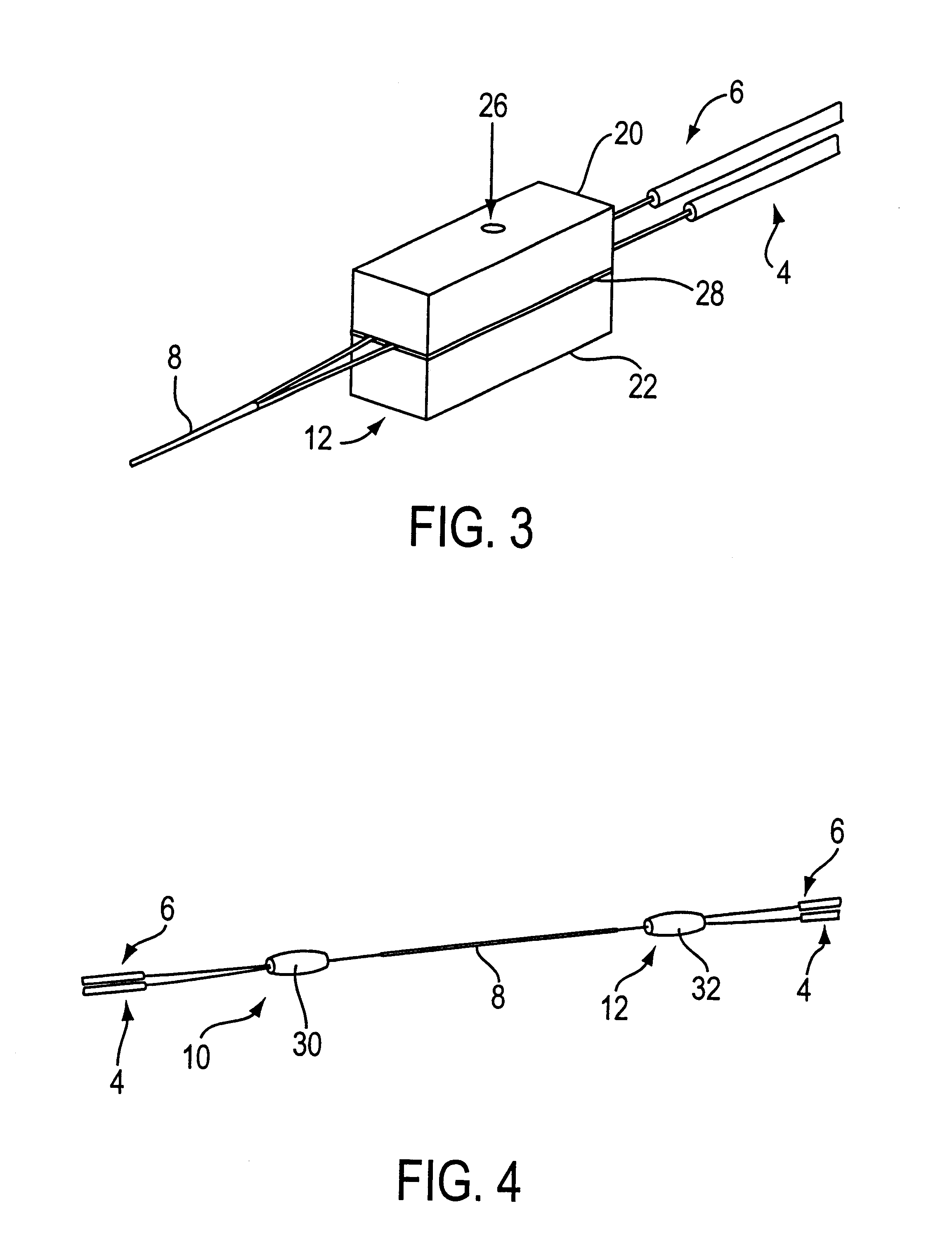
FIG. 3 is a form 20, 22 shown in place around the optical fibers 4, 6 at an anchoring location 12 outside the fused region 8. To create the anchoring point 12, pure liquid aluminum is injected into the form 20, 22 at aperture 26, and allowed to cool. As the aluminum cools, it safely chemically bonds to and compresses around the optical fibers 4, 6, although other materials may be used that do not chemically bond per se. That is, other materials may also be used to bond or secure to or compress around the optical fibers to form the anchoring points. In addition, the bonding material need not necessarily be poured, as explained in greater detail below in connection with the invention.

Further, forms / blocks may also not be necessary depending on the type of anchor point being produced. For example, when a liquid material is used for bonding, the liquid material may simply be poured on the optical fiber, device and / or fiber optic device. Alternatively, metal blocks can be used as well an...


PUM


Abstract

An apparatus includes a device having at least one exposed region. First and second metal seals bond and/or secure with, and surround, the exposed region of the device. An enclosure seals the device between the first and second metal seals. The enclosure has a first substrate and a second substrate, each with end surfaces including a deformable metal layer. The deformable metal layer seals the corresponding surfaces in response to the application of a compressive force and/or energy to the first and second substrates. The enclosure may be constructed to include a cavity, and/or constructed of relative short length. The enclosure may be used to secure to a portion of an optical fiber, fiber optic device and/or device, and/or may be used to encase a portion or all of an optical fiber, fiber optic device and/or device.

Description

1. Field of the InventionThe present invention relates to an apparatus and method for bonding optical fiber and / or device to external element using compliant material interface, and more particularly, to an apparatus and method for bonding an optical fiber and / or device to an external substrate for strength, support, and protection.2. Background of the Related ArtCurrently, various techniques exist for stabilizing an optical fiber and / or device to an external substrate. For example, one technique involves using an epoxy to affix the optical fiber to an external substrate. Another technique disclosed in U.S. Pat. No. 5,475,784 to Bookbinder, et al. encapsulates a segment of organic material of an optical component, such as a junction, by directly placing molten metal around the component and solidifying the metal.However, the resulting bonded optical fiber(s) or device according to these prior techniques often times is not properly protected and / or affixed. These processes are diffic...

Claims


Application Information

Patent Timeline
IPC IPC(8): G02B6/38G02B6/255G02B6/28G02B6/36G02B6/42
CPCG02B6/2551G02B6/2552G02B6/2835G02B6/3855G02B6/3861G02B6/3862G02B6/4248G02B6/36G02B6/3837G02B6/3887
Inventor BLOOM, CARY
Owner BLOOM CARY
Why Eureka
Try Eureka