Method and apparatus for non-propulsive fin control in an air or sea vehicle using planar actuation
- Summary
- Abstract
- Description
- Claims
- Application Information
AI Technical Summary
Problems solved by technology
Method used
Image


Examples
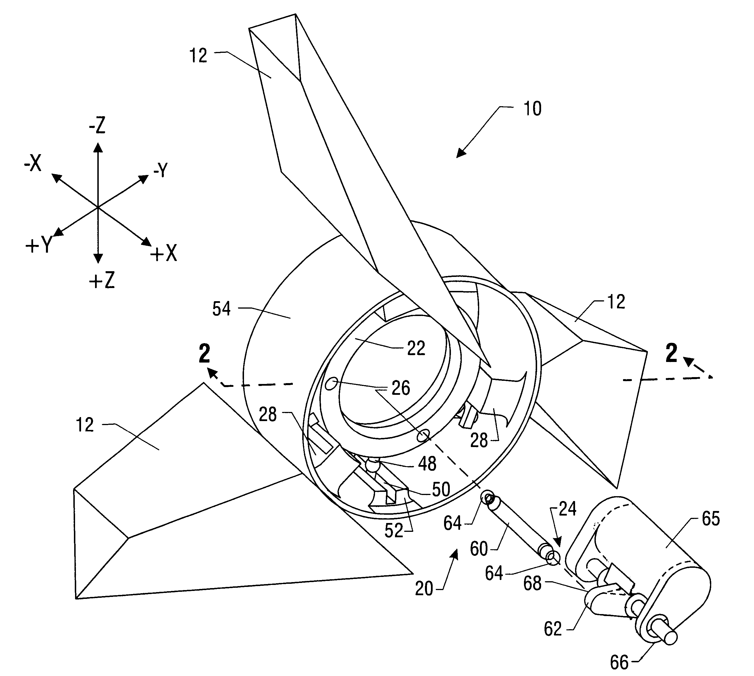
embodiment 10
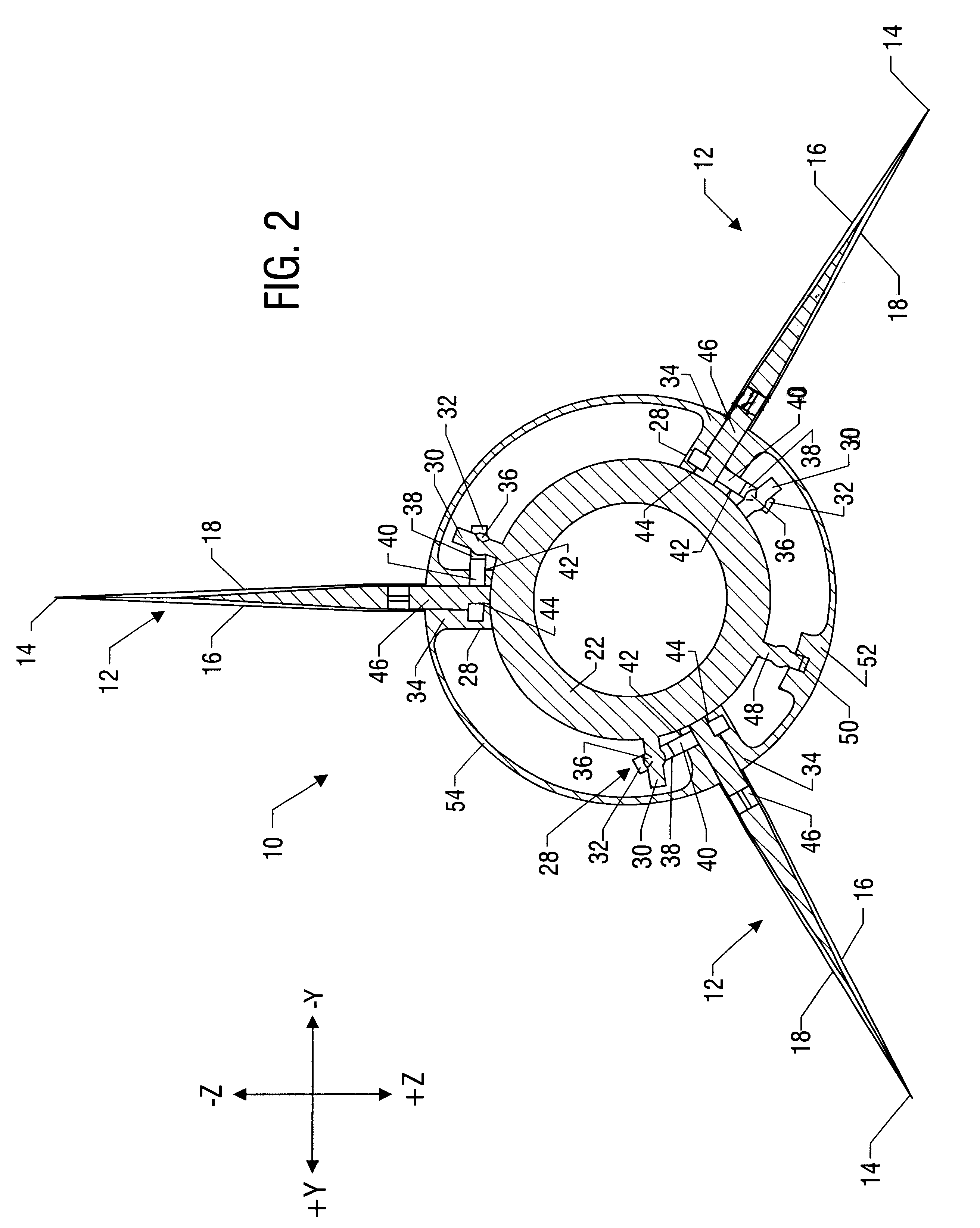
FIGS. 1-3 illustrate a particular embodiment 10 of an air or sea vehicle, non-propulsive fin control system constructed and operated in accordance with the invention. The control system 10 is for use with a missile. However, in alternative embodiments the control system 10 may be used with a guided bomb, a guided munition, and / or another air or sea vehicle employing non-propulsive fins. As shown best in FIG. 2, the control system 10 includes at least three non-propulsive fins 12, each of which provides a flight control surface 14 comprised of first and second faces 16 and 18, respectively. The number of flight control surfaces 14 is not material to the practice of the invention provided there are at least three. Thus, this particular embodiment may be used with any number of fins 12 greater than, or equal to, three. The flight control surfaces 14 control the pitch, yaw, and roll attitudes of the vehicle controlled by the control system 10.
Returning to FIG. 1, the control system 10 i...
embodiment 28
FIGS. 7-9 illustrate a non-propuslive fin control system 10' employing an alternative embodiment 28' of the linkage 28. The linkage 28' of this embodiment generally includes a rack 72, a rack guide 74, and a pinion gear 76. The rack 72 is operatively coupled to the actuation plane 22 by a pin 78 extending from the rack 72 into a socket 75 in the actuation plane 22. The pin 78 has a spherical head 85 that, in combination with the socket 75, permits properly constrained motion between the rack 72 and the actuation plane 22 as the actuation plane 22 is displaced. The rack 72 is operatively coupled to the pinion gear 76 by a toothed interface 84 such that the rack 72 and the pinion gear 76 form a rack and pinion. The actuation mechanism (not shown) may, in various embodiments, be electromagnetic, electromechanical, purely mechanical, hydraulic, or pneumatic.
embodiment 24
FIG. 16A illustrates, in part, an alternative embodiment 24' of the actuation mechanism 24 as employed in the embodiment 10'. This actuation mechanism 24' includes two plates 80 bracketing the actuation plane 22. Each point 26 in this particular embodiment is constructed from paired electromagnets 82. More particularly, the interior surface 83 of each plate 80 has mounted thereon at least three electromagnets 82. Both sides 86 of the actuation plane 22 have mounted thereon, opposed to the electromagnets 82 mounted on the plates 80, at least three electromagnets 82. The polarities of the paired electromagnets 82 may be manipulated so that the paired electromagnets 80 attract and repel in a predetermined pattern to displace the actuation plane 22 by pushing and pulling it. The mounting and powering of the electromagnets 80 will be implementation specific and may be any suitable technique known to the art. This embodiment of the actuation mechanism 24' may also be controlled using any ...
PUM
 Abstract
Description
Claims
Application Information