
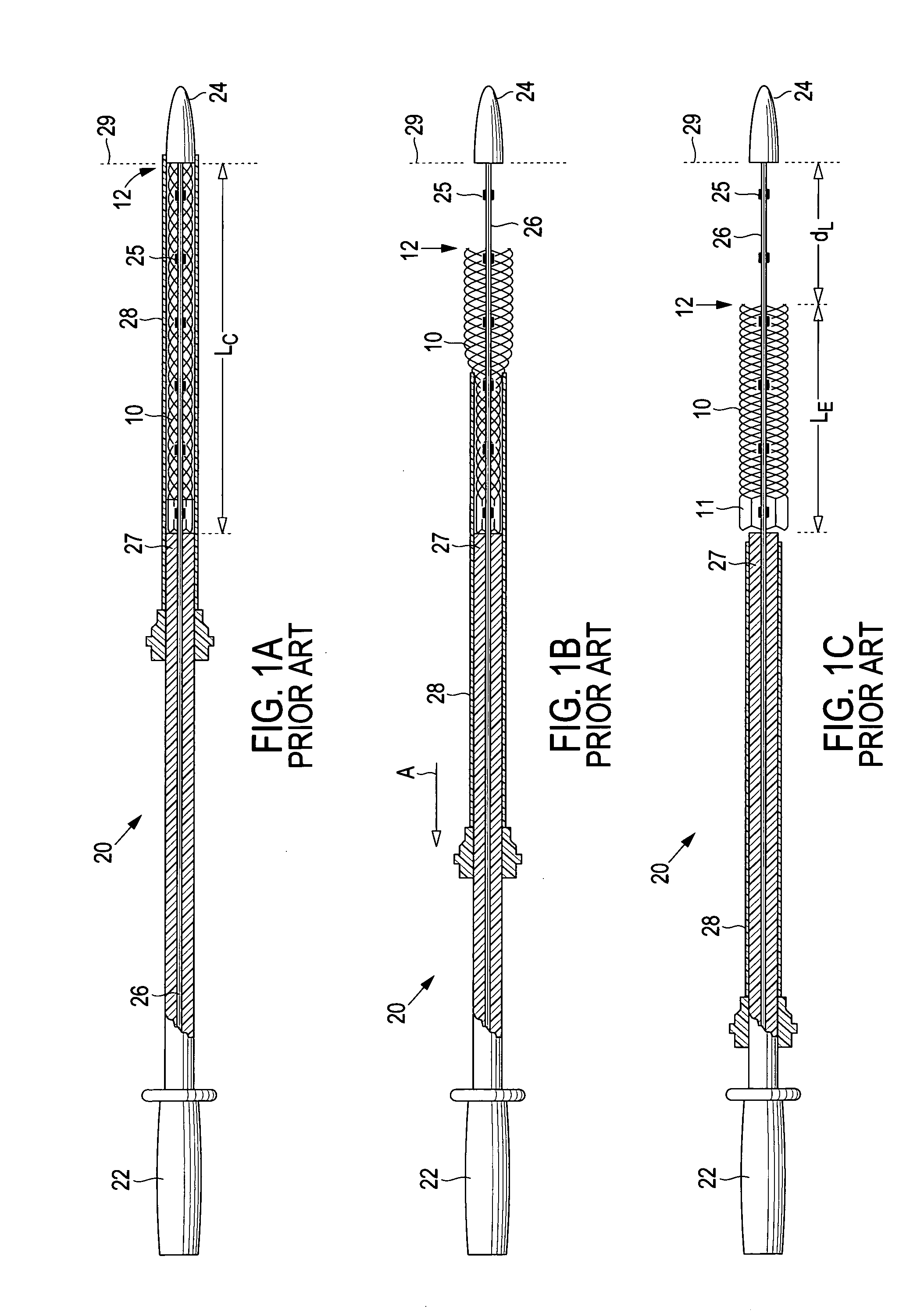
Delivery system and method for deployment of foreshortening endoluminal devices

a technology of endoluminal devices and delivery systems, which is applied in the field of delivery systems for endoluminal devices, can solve the problems of repeated practice, stent accuracy, and affecting the deployment accuracy of endoluminal devices

Active Publication Date: 2006-05-30
BOSTON SCI SCIMED INC
View PDF15 Cites 282 Cited by
  • Summary
  • Abstract
  • Description
  • Claims
  • Application Information

AI Technical Summary

Benefits of technology

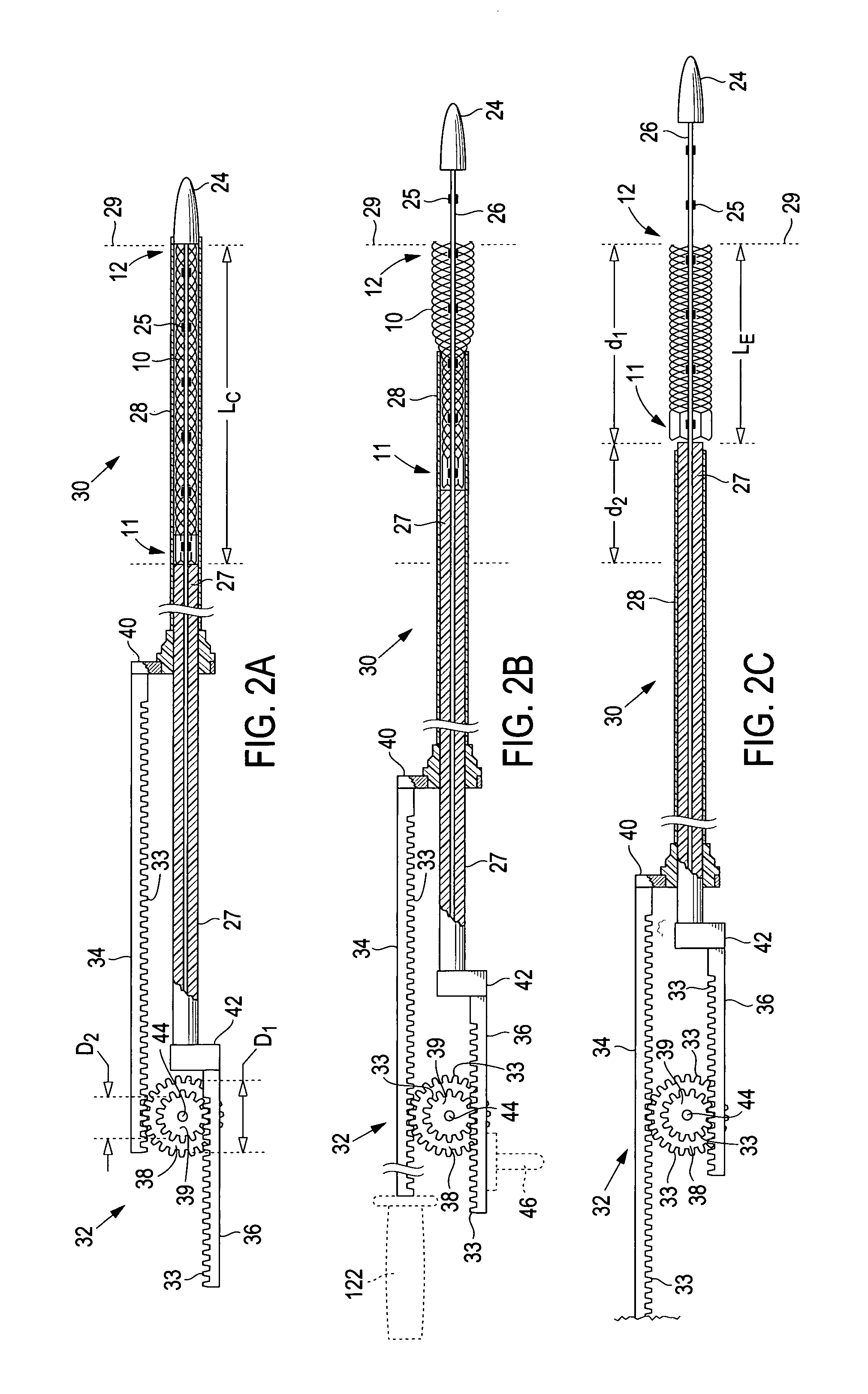
[0012](d2d1)is approximately equal to the foreshortening ratio. The linkage may provide mechanical advantage that enables a user to manipulate the linkage using less force than is required to simultaneously move the outer sheath in the first direction and the pusher in the second direction.

Problems solved by technology

Foreshortening may affect the deployment accuracy of endoluminal devices.
Deploying such stents with accuracy, therefore, takes repeated practice and is prone to error.

Method used


Image

  • Delivery system and method for deployment of foreshortening endoluminal devices
  • Delivery system and method for deployment of foreshortening endoluminal devices
  • Delivery system and method for deployment of foreshortening endoluminal devices

Examples


Embodiment Construction

[0033]The invention will next be illustrated with reference to the figures wherein similar numbers indicate the same elements in all figures. Such figures are intended to be illustrative rather than limiting and are included herewith to facilitate the explanation of the apparatus of the present invention.

[0034]Referring now to FIGS. 2A–2C, there is shown an exemplary delivery system 30 of this invention in various stages of deployment. Delivery system 30 comprises stent 10 in its compressed configuration, outer sheath 28 that radially surrounds the stent, pusher 27 positioned at the proximal end 11 of the stent, and a linkage 32 in communication with both the pusher and the outer sheath. Linkage 32 coordinates proximal retraction of outer sheath 28 with simultaneous distal advancement of pusher 27. Also shown in FIGS. 2A–2C is inner member 26, attached to an interface 42 at its proximal end and extending axially through stent 10 and pusher 27 to a connection with tip 24 at its dista...


PUM


Abstract

A delivery system comprising an endoluminal device, an outer sheath that radially surrounds the endoluminal device, a pusher positioned at one end of the endoluminal device, and a linkage between the pusher and the outer sheath that coordinates movement of the outer sheath in a first direction with simultaneous movement of the pusher in a second direction opposite the first direction. This delivery system is particularly useful for endoluminal devices that foreshorten, and may comprise the outer sheath moving a first distance (d1) and the pusher moving a second distance (d2), where d2 / d1 is approximately equal to the foreshortening ratio. The delivery system of this invention enables a foreshortening device, such as a vena cava filter, or stent, graft, or combination thereof, to be deployed with its end in a precise deployment location without foreshortening causing the end to move from the deployment location as the stent expands.

Description

TECHNICAL FIELD[0001]This invention relates generally to delivery systems for endoluminal devices, and, more specifically, to delivery systems for endoluminal devices that undergo a decrease in length when being expanded from a radially compressed configuration.BACKGROUND OF THE INVENTION[0002]Endoluminal devices comprise the general category of devices, such as stents, grafts, combinations thereof commonly referred to as stent-grafts or endoluminal prostheses, vena cava filters, and the like, that may be implanted in a body lumen. Endoluminal devices may be implanted by so-called “minimally invasive techniques” in which the prosthesis, restrained in a radially compressed configuration by a sheath or catheter, is delivered by a deployment system or “introducer” to the site where it is required. The introducer may enter the body through the patient's skin, or by a “cut down” technique in which the entry lumen, such as a blood vessel, is exposed by minor surgical means. When the intro...

Claims


Application Information

Patent Timeline
Patent Type & Authority Patents(United States)
IPC IPC(8): A61F2/06A61B17/00A61F2/04A61F2/82A61F2/84
CPCA61F2/95A61M2025/1068A61F2002/9517A61F2/9517
Inventor WELDON, JAMESYAMPOLSKY, ILYA
Owner BOSTON SCI SCIMED INC
Learn More