Spare-tire fastening structure

Inactive Publication Date: 2001-06-26
NEWFREY
View PDF10 Cites 22 Cited by
  • Summary
  • Abstract
  • Description
  • Claims
  • Application Information

AI Technical Summary

Benefits of technology

Accordingly, an object of the present invention is to provide a spare-tire fastening structure which maintains an advantage that the spare-tire can be easily be fastened by inserting a bolt member into a nut member and further provides additional advantages that the nut member can also easily be mounted on the spare-tire receiving section and the nut member cannot be disengaged from the spare-tire receiving section when the bolt member is inserted into the nut member. Another object of the present invention is to provide a spare-tire fastening structure which is composed of the nut member and the bolt member and allows a service tool such as a screwdriver to be held thereby.
As described above, since the nut member is mounted on the support member by inserting the housing stem from its end opposite to the flange into the mounting hole of the support member and pressing the housing stem thereinto until the flange is brought into surface-contact with the support member, the nut member can be mounted on the support member in the spare-tire receiving section only by a simple pressing operation, and on the other hand, the bolt member can be engaged with the nut member only by pressing the bolt member into the nut member in the same direction as of the pressing operation for mounting the nut member, that is, both of the nut member and the bolt member can be handled from the same side or one side, and in addition, since the flange of the nut member is brought into surface-contact with the upper surface of the support member in the spare-tire receiving section so as to work as a stopper, the nut member is never disengaged from the support member when the bolt member is inserted into the nut member so as to press the nut member downward. Since the bolt member is engaged with the nut member by pressing the bolt member into the nut member, the spare-tire can be easily fastened to the spare-tire receiving section.
According to the spare-tire fastening structure of the present invention, since the nut member is mounted on the support member by inserting the housing stem from its end opposite to the flange into the mounting hole of the support member and pressing the housing stem thereinto until the flange is brought into surface-contact with the support member, the nut member can be mounted on the support member in the spare-tire receiving section only by a simple pressing operation, and on the other hand, the bolt member can be engaged with the nut member only by pressing the bolt member into the nut member in the same direction as of the pressing operation for mounting the nut member, that is, both of the nut member and the bolt member can be handled from the same side or one side, and in addition, since the flange of the nut member is brought into surface-contact with the upper surface of the support member in the spare-tire receiving section so as to work as a stopper, the nut member is never disengaged from the support member when the bolt member is inserted into the nut member so as to press the nut member downward. Since the bolt member is engaged with the nut member by pressing the bolt member into the nut member, the spare-tire can be easily fastened to the spare-tire receiving section.

Problems solved by technology

This operation takes long time for screwing the bolt member and accordingly, makes poor working efficiency.
The fastening structure disclosed in the above Utility Model publication, however, is configured to attach the nut member to the boss as the support member in the spare-tire receiving section from an under surface side of the boss, and this makes an attaching operation troublesome since it is required to stretch one hand to a back side of the boss.
Further, since the nut member is attached to the boss from the under surface side thereof, an inserting force of the bolt member into the nut member is applied to the nut member in a direction to disengage it from the boss, and therefore this structure is not preferable since there is a fear that the nut member might be disengaged from the boss by a strong inserting force applied thereto by the bolt member.
This fastening structure requires a welding operating for fixing the housing of the nut member to the spare-tire receiving section and an assembling operation for attaching the metal half nut blocks and the metal spring to the housing to be held therein after the housing has been fixed to the spare-tire receiving section, and further, the metal members may cause a rusting problem.

Method used


Image

  • Spare-tire fastening structure
  • Spare-tire fastening structure
  • Spare-tire fastening structure

Examples


Embodiment Construction

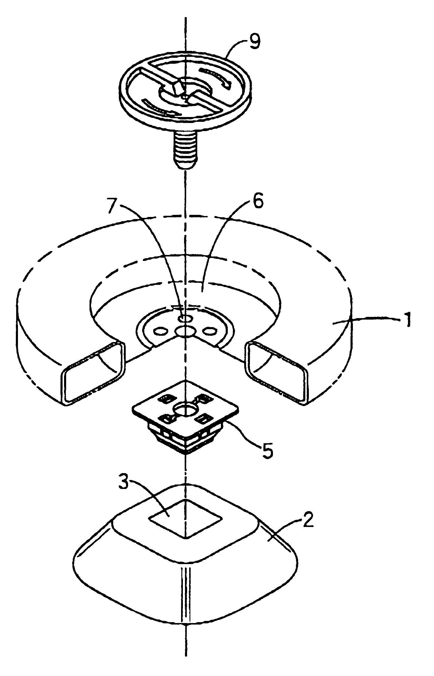
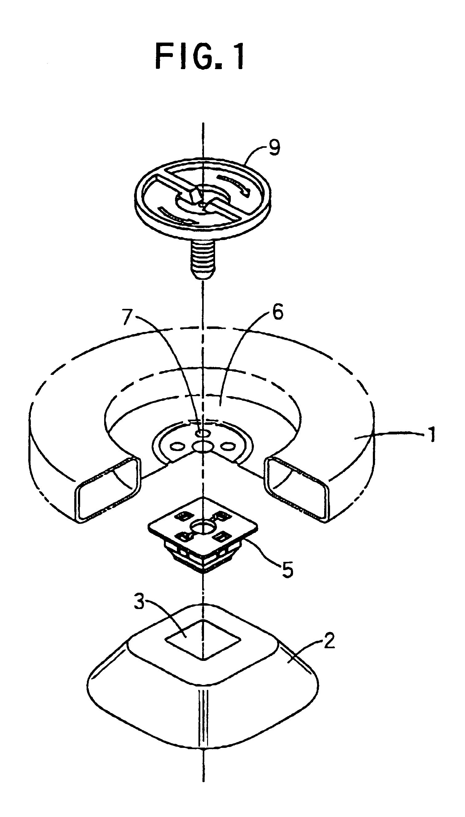
Embodiments of the present invention will be described in detail with reference to the drawings attached herewith. FIGS. 1 to 15 show a configuration of the spare-tire fastening structure according to an embodiment of the present invention, and FIGS. 16 to 18 show an operation or process to fasten a spare-tire to a spare-tire receiving section using the spare-tire fastening structure of the present invention. Further, FIGS. 19 to 22 show an alternative embodiment of the bolt member.

Referring to FIG. 1, a spare-tire 1, which is shown by a partially cutaway view for the convenience of illustration, is fastened to a support member or a bracket 2 provided in a spare-tire receiving section of an automobile, by the spare-tire fastening structure according to the present invention. The spare-tire fastening structure is composed of a nut member 5 which is inserted into and fixed to a rectangular fixing hole 3 formed on the support member or the bracket 2, and a bolt member 9 which is to be ...


PUM


Abstract

A spare-tire fastening structure is for fastening a spare-tire 1 to a support member (bracket 2) in a spare-tire receiving section. The fastening structure comprises a nut member 5 and a bolt member 9. The nut member 5 comprises a plastic housing 10 including a flange 13 and a hollow stem 14 extending from the flange 13; and a plastic nut body 11 including two screw segments 23 forming one screw as a whole, and spring portions 22 each extending from each of the screw segments 23 to a base portion 21 to bias or push each of the screw segments 23 up from the base portion 21; wherein an outer surface of the housing stem 14 is formed with engagement pawls 17 which are associated with the flange 13 to sandwich or grip the support member between the pawls 17 and the flange 13; and the nut member 5 is mounted on the support member by inserting the housing stem 14 from an end thereof opposite to the flange 13 into a mounting hole of the support member and pressing the housing stem 14 thereinto until the flange 13 is brought into surface-contact with the support member; wherein, under a condition where a mounting hole of a spare-tire wheel is aligned with the nut member 5, the bolt member 9 is pressed through the spare-tire wheel 6 into the nut member 5 in the same direction as of a pressing operation for mounting the nut member 5, so that the bolt member 9 is engaged with the nut member 5 so as to fasten the spare-tire to the support member.

Description

1. Field of InventionThe present invention relates to a spare-tire fastening structure for fastening a spare-tire to a support member in a spare-tire receiving section by engaging a bolt member with a nut member anchored to the support member such as a bracket.2. Description of Prior ArtGenerally, when a spare-tire is to be fastened to a support member such as a bracket in a spare-tire receiving section of an automobile, a mounting hole of a wheel of the spare-tire is aligned with a nut welded to the support member, and then a bolt member is inserted through the mounting hole and is screwed into the nut. This operation takes long time for screwing the bolt member and accordingly, makes poor working efficiency. In order to solve this problem, Japanese Utility Model Registration No. 2583778 (Japanese Utility Model Publication No. 05-022279) discloses a improved fastening structure in which a plastic nut member is fixed to a boss in a spare-tire receiving section and a bolt member is i...

Claims


Application Information

Patent Timeline
IPC IPC(8): B62D43/00B62D43/10F16B37/04
CPCB62D43/10
Inventor MARUYAMA, T.
Owner NEWFREY
Why Eureka
Try Eureka