Apparatus to enhance cooling of electronic device

a technology of electronic devices and accessories, applied in the direction of electrical apparatus casings/cabinets/drawers, instruments, etc., can solve the problems of reducing the reliability of components or systems, affecting the performance of electronic devices, and causing the failure of system components 300

Inactive Publication Date: 2001-07-03
HEWLETT PACKARD DEV CO LP
View PDF24 Cites 54 Cited by
  • Summary
  • Abstract
  • Description
  • Claims
  • Application Information

AI Technical Summary

Benefits of technology

FIG. 10 is an isometric drawing of an air duct useful

Problems solved by technology

Many electronic devices have inadequate thermal management.
They either get too hot for comfort or so hot that component or system reliability is reduced.
The result of this approach is that the system components 300 are heated by the warm heat producing component 240 air flow and this heating may cause some of the system components 300 to fail prematurely.
Additionally, th

Method used


Image

  • Apparatus to enhance cooling of electronic device
  • Apparatus to enhance cooling of electronic device
  • Apparatus to enhance cooling of electronic device

Examples


Embodiment Construction

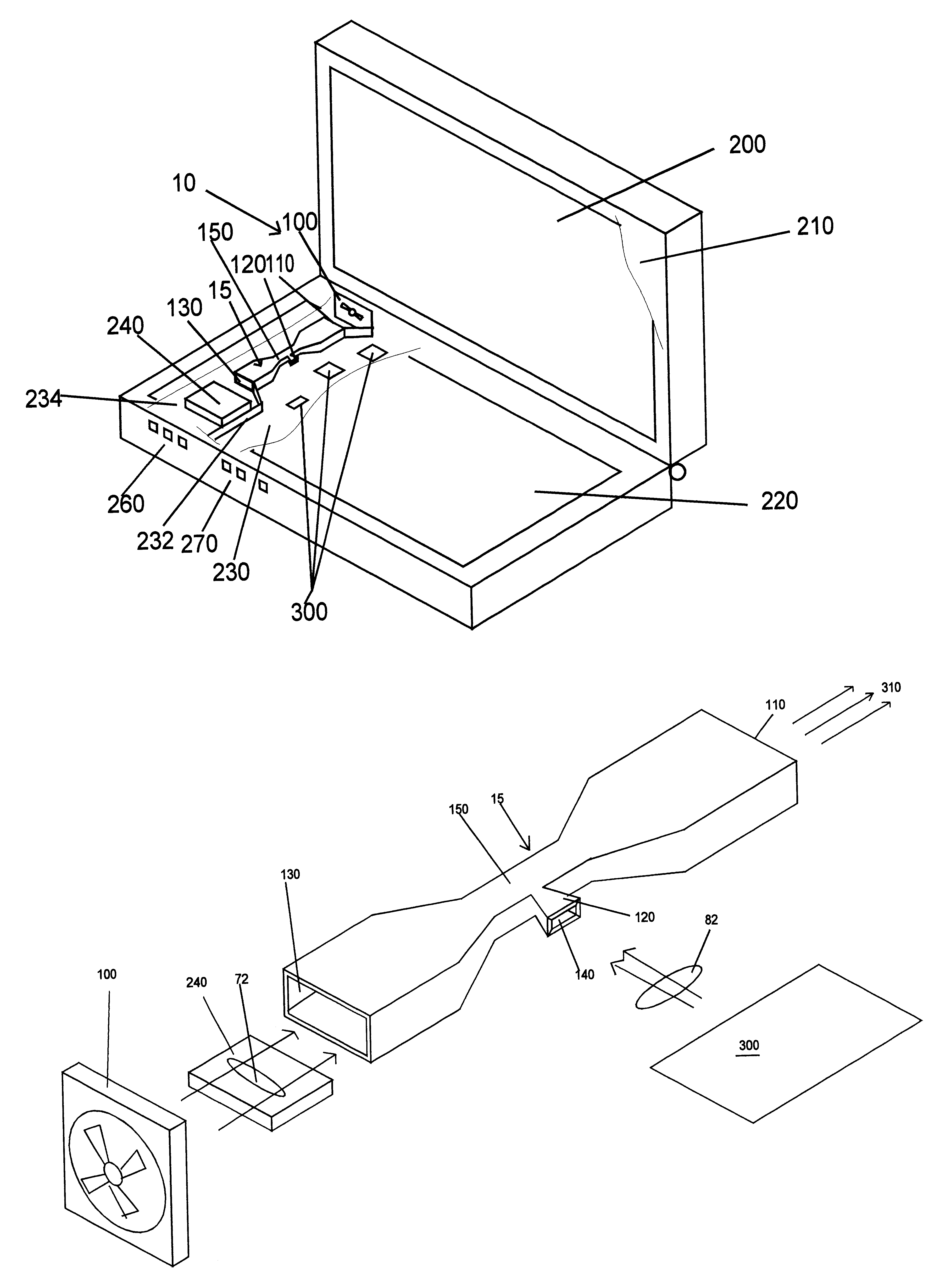
The invention solves a difficult cooling problem in electronic devices in an elegant manner. Separate cooling flows are created using a venturi vent in which a heat producing component, such as a CPU, microprocessor or processor module, is cooled independent of the rest of the system components. Additionally, this venturi vent technique extends to solve other difficult thermal issues. The invention addresses the need for separate air flows by using an air-moving device, such as a fan or blower, to create an air flow having an air velocity and then a restriction chamber to create a low pressure zone using the Bernoulli principle to create a vacuum air flow in a venturi vent which is used to evacuate either warm air from inside the product or to draw in cooler air from outside the product.

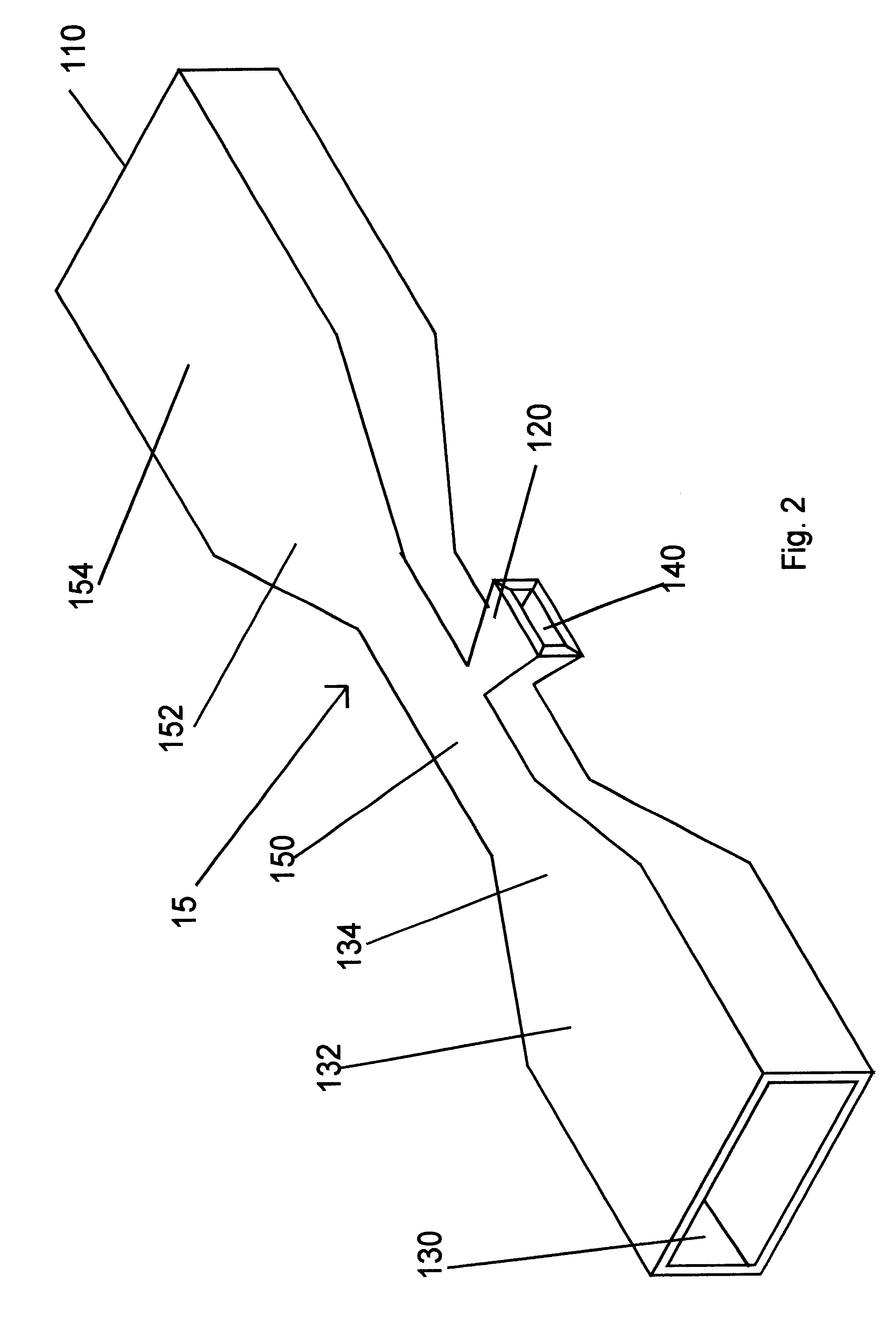
FIG. 2 illustrates an air duct 15 that comprises a venturi vent 120. The venturi vent 120 has an opening 140, that is preferably flared, and which helps to couple and operatively engage air external ...


PUM


Abstract

An electronic device has at least one component that is capable of generating a quantity of heat. The electronic device further has an air-moving device and an air duct. The air moving device is capable of creating a flow of air that removes a portion of the quantity of heat. The flow of air enters the air duct. The air duct has a restriction chamber that includes a venturi vent in which the flow of air into the duct and through the restriction chamber creates a new flow of air into the venturi vent. The new flow of air into the venturi vent does not pass over the at least one component in the electronic device.

Description

This invention relates to a heat transfer system. More specifically, it relates to using a venturi to create separate air flows in an electronic device to cool components.Many electronic devices have inadequate thermal management. They either get too hot for comfort or so hot that component or system reliability is reduced. Many customers of electronic devices are starting to recognize that manufacturers are cutting corners in thermal design as processor speeds keep increasing. FIGS. 1A through 1D represent different prior art approaches using fans by several manufacturers.FIG. 1A illustrates one prior art approach to cooling a heat producing component 240 in an electronic device such as a notebook computer. An air-moving device 100, such as a fan or blower, blows air across the heat producing component 240 and the air then exits the electronic device. While this approach cools the heat producing component, it ignores the rest of the system components 300 which typically comprise on...

Claims


Application Information

Patent Timeline
IPC IPC(8): G06F1/20H01L23/34H01L23/467H05K7/20
CPCG06F1/203H01L23/467Y10S165/903H01L2924/0002H01L2924/00
Inventor STERNER, JOHN R.
Owner HEWLETT PACKARD DEV CO LP
Why Eureka
Try Eureka