Hose coupling

a technology of hose coupling and flexible hose, which is applied in the direction of hose connection, braking system, braking components, etc., can solve the problems of system air loss, sharp edges on the end of flexible hoses coming into contact with o-rings, etc., to facilitate the attachment of flexible hoses, facilitate the radial expansion and contraction of the grip/release mechanism, and facilitate tube attachment.

Inactive Publication Date: 2001-07-03
KILGORE MFG
View PDF11 Cites 29 Cited by
  • Summary
  • Abstract
  • Description
  • Claims
  • Application Information

AI Technical Summary

Benefits of technology

One feature of the present invention is that it includes a tube support having at least one radially outwardly extending grip ring formed thereon, and a grip/release mechanism having at least one radially inwardly extending grip ring that is formed thereon. The flexible hose can be selectively and replaceably captured between the tube support and the grip/release mechanism, so that the gripping ring of the tube support engages the interior surface of the flexible hose, and the radially inwardly extending grip ring of the grip/release mechanism engages the hose's exterior surface. This dual, interior-exterior gripping provided by the present invention has the advantage of securely gripping the flexible hose in a manner that retains the flexible hose securely on to the coupling, especially when an a

Problems solved by technology

Couplings of this type have some inherent problems.
One problem is the sharp edges on the end of the flexible brake hoses come in contac

Method used


Image

  • Hose coupling
  • Hose coupling
  • Hose coupling

Examples


second embodiment

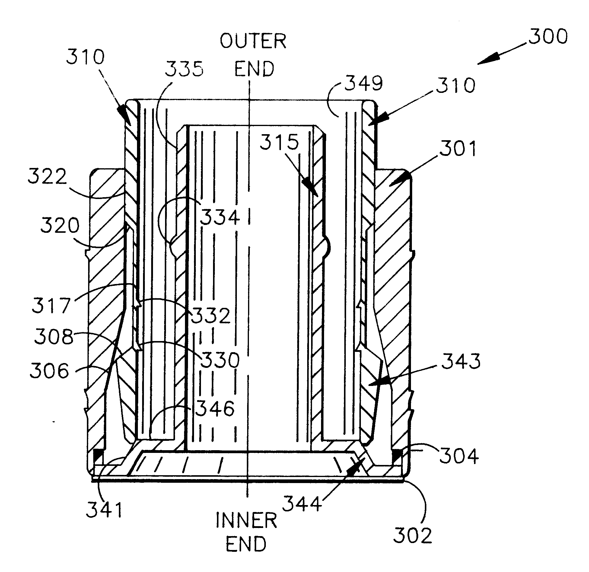
Turning now to FIG. 11, a manifold 210 is shown, into which the coupling 200 is fitted. The manifold 210 is part of the truck. The manifold is typically made of some sort of metal such as aluminum, with plastic injection moldings coming out of it. The manifold 210 includes a manifold air passageway 212. The second embodiment includes a housing 214, a release mechanism 226, a seal 236, and a tube support 220.

The actual outer housing 214 of the coupling 200 is generally cylindrical and includes an axially-extending outer cylindrical surface 216. A free floating air space exists between the bottom of the generally hollow housing 214 and manifold 210. The housing 214 includes an interior passageway 241 into which the other components of the coupling 200 are mounted. One of the components, the tube support 220, includes a spring portion 221 which presses against the axially outwardly facing, radially extending surface 223 of manifold 210. The axially inner portion of housing 214 contains...

third embodiment

A third embodiment is shown on the left side of FIG. 13. FIG. 13 is a split drawing where the coupling shown to the right of axis A is coupling 200 of FIG. 11, and the coupling shown to the left of axis A is coupling 700 of the present invention. Each embodiment has the same components with some configuration differences.

Several differences exist between coupling 200 and coupling 700. One difference is that tube support 703 is not slotted, whereas tube support 220 contains slots 244a, 244b. Spring portions 702 and 221 also have a different configuration. The third embodiment spring base 702:

(1) extends axially inwardly to about the axially outwardly facing surface 723 of manifold 790;

(2) then bends, at almost a right angle to extend radially outwardly;

(3) then bends about 30 degrees upwardly to form a ramping surface 707;

(4) then bends back at about 150 degrees; and

(5) then bends about 30 degrees to extend radially inwardly, perpendicular to longitudinal axis A. At this point it for...


PUM

PropertyMeasurementUnit
Forceaaaaaaaaaa
Diameteraaaaaaaaaa
Flexibilityaaaaaaaaaa

Abstract

A hose coupling secures a flexible hose member having a radially outwardly facing exterior hose surface and a radially inwardly facing interior hose surface. The hose coupling includes a housing having a radially outwardly facing exterior surface and a radially inwardly facing interior surface defining a longitudinal passageway, a first axial end, and a second axial end. The interior surface includes a first ramped portion and a first seating portion. A tube support member has a tube portion disposed in the interior longitudinal passageway of the housing and a base portion fixedly coupled to the housing at the second axial end of the housing. The base portion has a seal seat region, and the tube portion has a radially outwardly facing exterior surface that includes a first grip ring for supporting the interior hose surface. The first grip ring is circumferentially disposed about the exterior hose surface. A seal is disposed between the first seating portion of the housing and the seal seat region of the tube support member. A grip/release mechanism is disposed in the longitudinal passageway of the housing concentrically exteriorly of the tube portion of the tube support member. The grip/release member is axially moveable relative to the housing and has a third axial end, a radially inwardly facing, axially extending interior surface defining an interior longitudinal passageway, and a radially outwardly facing, axially extending exterior surface. The grip/release member interior surface includes a circumferentially disposed sealing grip ring and a circumferentially disposed barbed grip ring disposed toward the third axial end relative to the grip ring. The sealing grip ring exerts a compressive force on the exterior hose surface and the barbed grip ring grips the exterior hose surface by exerting an expansive force. The grip/release mechanism exterior surface includes a second ramped portion.

Description

II. TECHNICAL FIELD OF THE INVENTIONThe present invention relates to a hose coupling and more particularly to a relatively inflexible hose coupling to which a flexible hose can be connected. The hose coupling has special adaptability for use in connection with high pressure air hoses of the type that as are used in connection with an air system on a vehicle such as a locomotive, railroad car, or truck and trailer having air brake lines.III. BACKGROUND OF THE INVENTIONMany circumstances exist wherein a person wishes to couple a flexible hose, such as a flexible air line, to an inflexible coupling, such as a coupling made from steel or brass. These circumstances typically arise in fluid systems that carry a gas or liquid between two points; and fluid systems that employ a gas or air to perform work, such as air brake systems, pneumatic systems and hydraulic systems. One particular circumstance where it is desirable to couple a flexible fluid carrying hose to an inflexible coupling is ...

Claims


Application Information

Patent Timeline
IPC IPC(8): F16L33/22
CPCB60T17/043F16L33/227
Inventor HAGAN, DAVID G.
Owner KILGORE MFG
Why Eureka
Try Eureka