Motor

a motor and motor body technology, applied in the direction of magnetic circuit rotating parts, magnetic circuit shape/form/construction, instruments, etc., can solve the problems of loss of compactness of the motor, large outside dimension of the motor, and long length of the entire motor including the pressurizing means

Inactive Publication Date: 2001-07-03
CANON KK +1
View PDF13 Cites 43 Cited by
  • Summary
  • Abstract
  • Description
  • Claims
  • Application Information

AI Technical Summary

Problems solved by technology

However, since, in the above-mentioned conventional step motor, the case 3, bobbin 101, stator coil 105, and the stator yoke 106 are coaxially placed on the outer periphery of the rotor, such a disadvantage that the outside dimension of motor becomes large arose.
Therefore, a length the entire motor including the pressurizing means becomes longer and the compactness of motor is lost.
Further, looseness between the rotor shaft and the bearing portion generates a larger working noise.

Method used


Image

  • Motor
  • Motor
  • Motor

Examples


Embodiment Construction

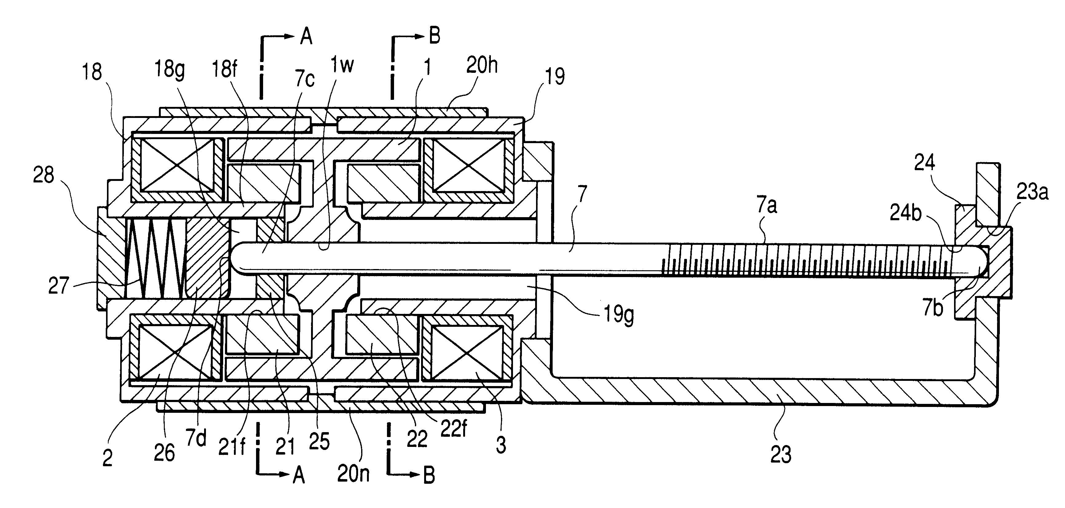
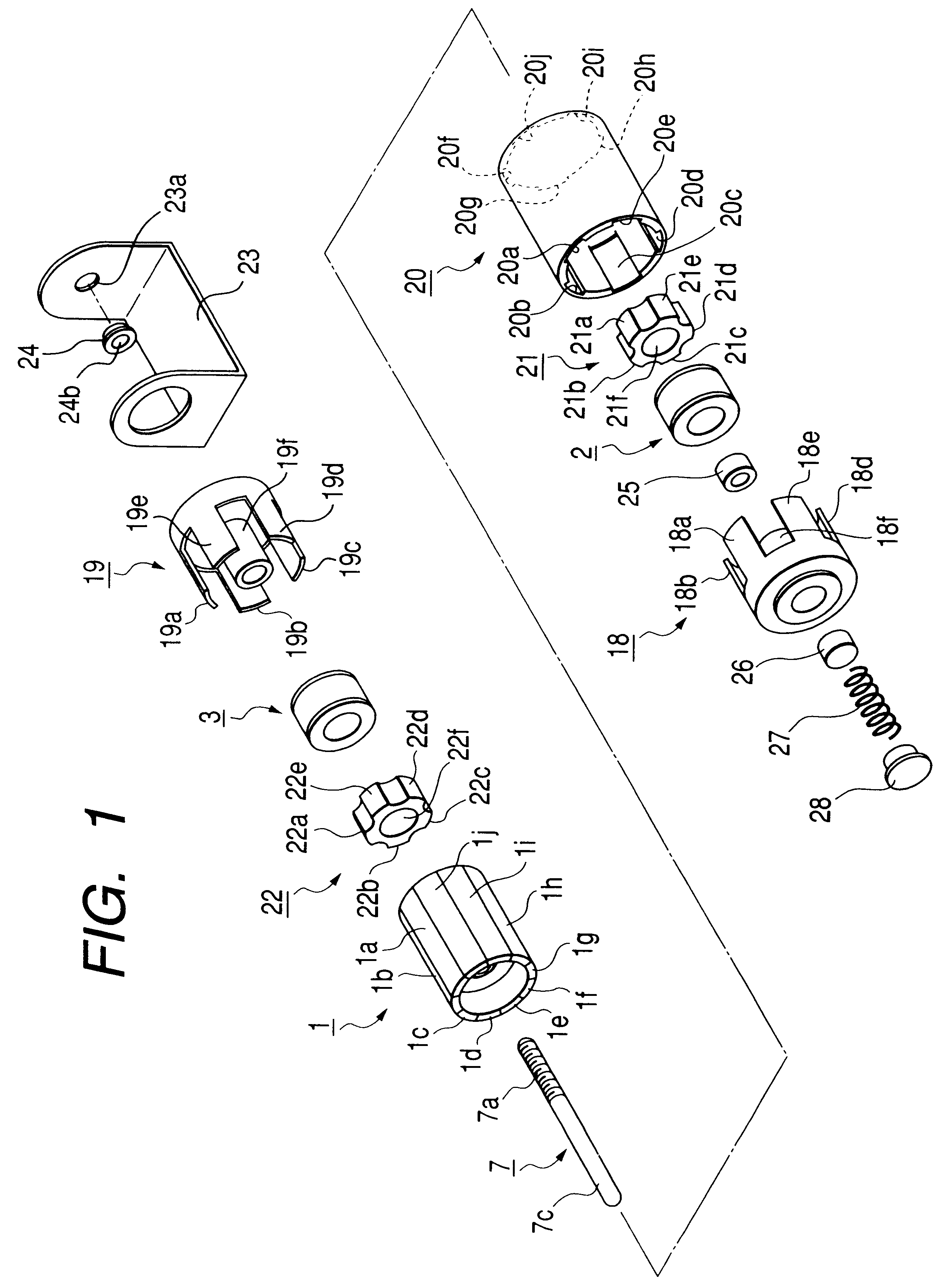
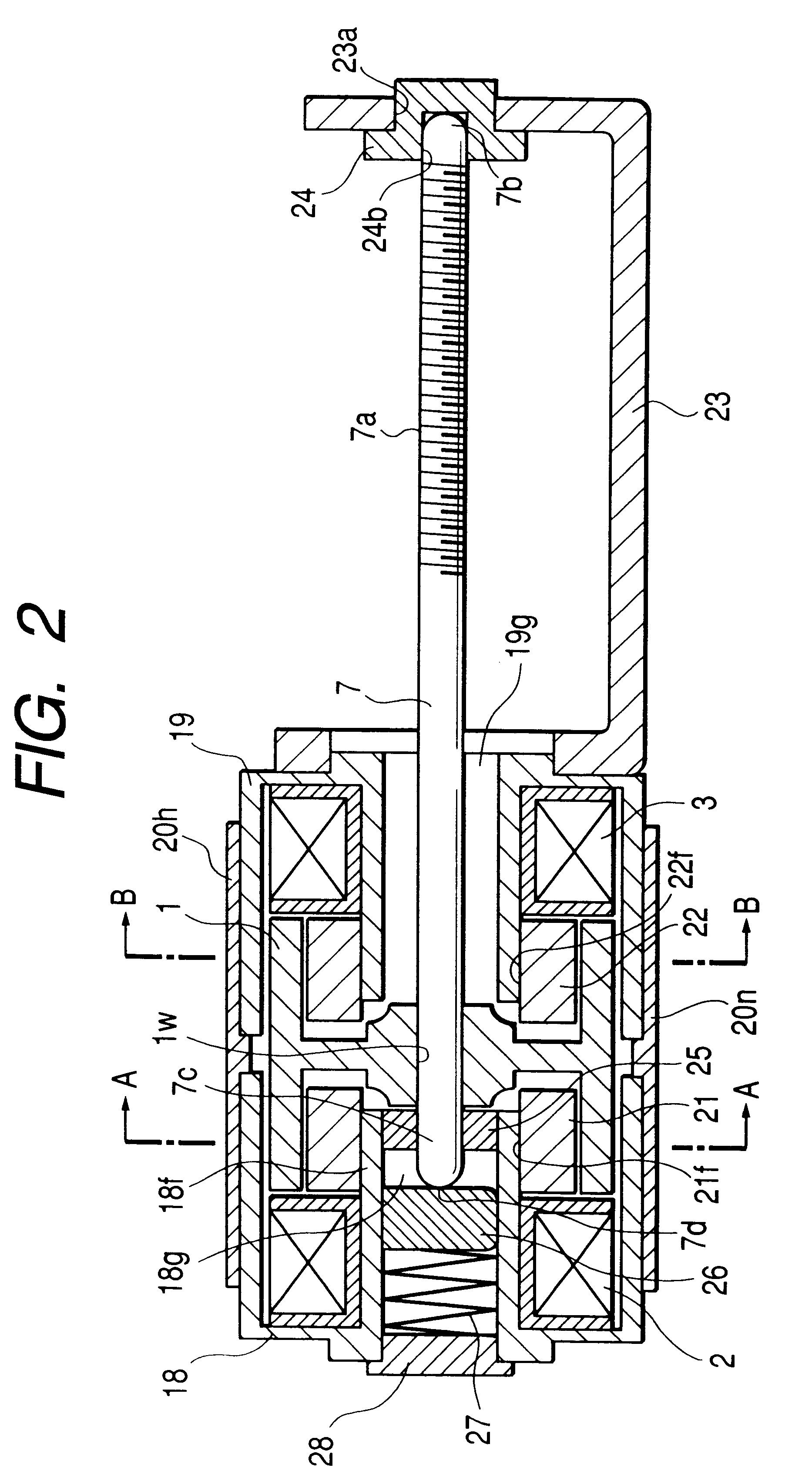
of the present invention will be described below, the basic configuration of a step motor according to the present invention is described with reference FIGS. 1, 2, 3A to 3H and 4.

FIG. 1 is an exploded perspective view of a step motor, FIG. 2 is a cross-sectional view of an assembled step motor in the axial direction, FIGS. 3A to 3D are cross-sectional views taken along the line A--A and FIGS. 3E to 3H are cross-sectional views taken along the line B--B in FIG. 2, and FIG. 4 is a perspective view of a connecting ring partially shown with a cross-section.

In FIGS. 1, 2, 3A to 3H and 4, the reference numeral 1 denotes a cylindrical magnet. In the magnet 1 that is a rotor, the outer periphery is divided into n parts (ten parts in the present example) to form polarized portions 1a, 1b, 1c, 1d, 1e, 1f, 1g, 1h, 1i, and 1j alternately polarized by the S pole and the N pole. The polarized portions 1a, 1c, 1e, 1g, and 1i are polarized by the S poles and the polarized portions 1b, 1d, 1f, 1h, ...


PUM


Abstract

A motor includes a magnet formed in a cylindrical shape and divided in the circumferential direction in at least the outer periphery and alternately polarized to different poles, a first coil, a magnet and a second coil placed in the axial direction of the magnet, a first outer magnetic pole opposed to the outer periphery of the magnet and a hollow-shaped first inner magnetic pole opposed to the inner periphery of the magnet, excited by the first coil respectively, a second outer magnetic pole opposed to the outer periphery of the magnet and a hollow-shaped second inner magnetic pole opposed to the inner periphery of the magnet, excited by the second coil respectively, a rotatable rotary shaft integral with the magnet, and a pressurizing device for pressurizing the rotary shaft in the axial direction, the pressurizing device being placed in the hollow cylindrical portion of the first inner magnetic pole. A motor having a high output, a compact shape and small working noises is provided.

Description

1. Field of the InventionThe present invention relates to a motor formed in an ultra-compact shape.2. Related Background ArtA motor formed as a compact motor is conventionally well known as, for example, a compact cylindrical step motor shown in FIG. 7. A stator 102 of the step motor is formed in such a manner that a stator coil 105 is coaxially wound around a bobbin 101, the bobbin is stationarily sandwiched between two stator yokes 106 in the axial direction, stator teeth 106a and 106b are alternately placed on the stator yoke 106 in the circumferential direction of the bobbin along the inner surface thereof, and that the stator yoke 106 integrated to the stator tooth 106a or 106b is fixed to the case 103.A flange 115 and a bearing 108 are fixed to one of two cases 103 and another bearing is fixed to the other case. A rotor 109 is composed of a rotor magnet 111 fixed to a rotor shaft 110. The rotor magnet is rotatably supported between two bearings 108.A mechanism has been propose...

Claims


Application Information

Patent Timeline
Patent Type & Authority Patents(United States)
IPC IPC(8): H02K7/06H02K37/12H02K5/167H02K37/24H02K1/14H02K1/27H02K37/00H02K16/04H02K16/00
CPCH02K1/145H02K1/2793H02K5/1672H02K37/24H02K16/04H02K37/125H02K7/06H02K1/2795
Inventor AOSHIMA, CHIKARAKUROSAWA, AKIRA
Owner CANON KK
Why Eureka
Try Eureka