

Configurable data converter
a data converter and configurable technology, applied in the field of analogtodigital (a/d) and digitaltoanalog (d/a) converters, can solve the problems of additional power consumption, reconfiguration of time slots, and additional space for additional components
Inactive Publication Date: 2001-07-03
LUCENT TECH INC
View PDF1 Cites 14 Cited by
- Summary
- Abstract
- Description
- Claims
- Application Information
AI Technical Summary
Problems solved by technology
Unfortunately, to change such systems having fixed time slot configurations for A / D and / or D / A input and output with respect to the data frame synch signal, the embedded circuit must be redesigned with the development of a new chip.
For instance, to add an A / D and / or D / A channel beyond those previously included in a device, or to increase the sample length of a particular converter beyond its previous maximum expected length, additional space for additional components, reconfiguration of time slots, and / or additional power consumption will be required.
Method used
View moreImage
Smart ImageViewing Examples

Examples
example configuration # 1
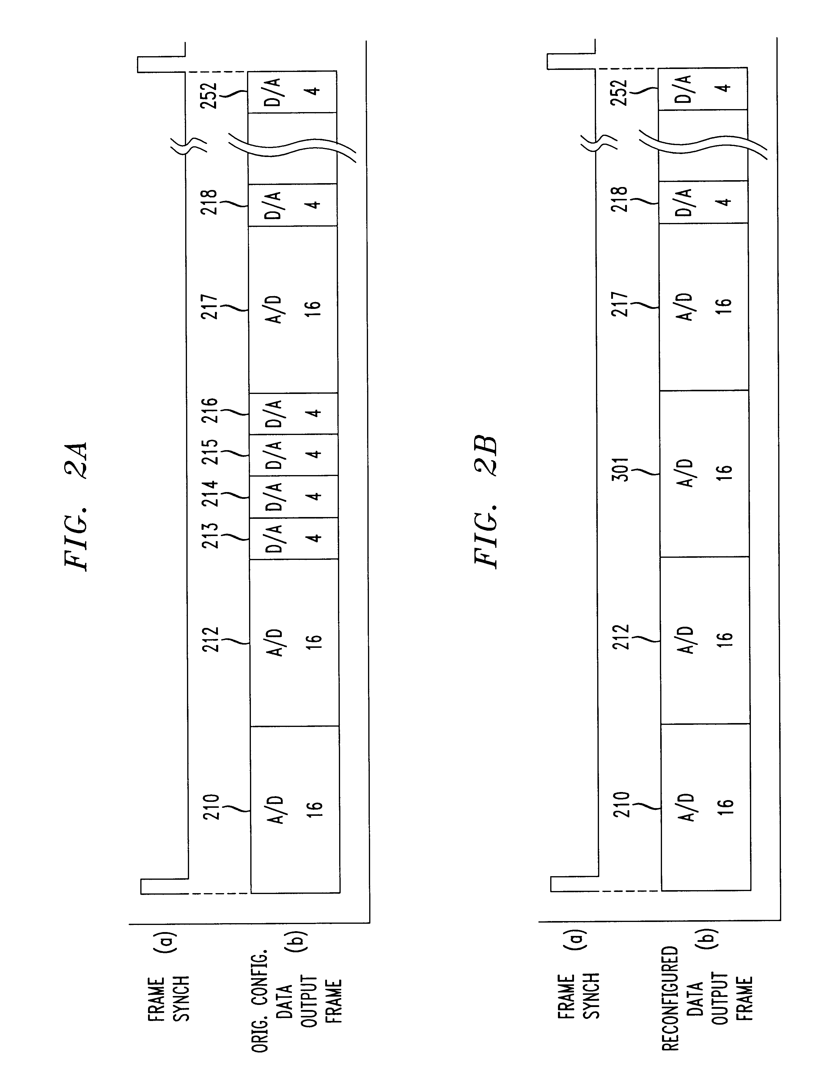
EXAMPLE CONFIGURATION #1
Multiple A / D and D / A Conversions Where A / D Conversions are Fixed at a 13-bit Level
example configuration # 2
EXAMPLE CONFIGURATION #2
Single A / D Input Source at Maximum Conversion Rate
example configuration # 3
EXAMPLE CONFIGURATION #3
Single D / A Output at Maximum Conversion Rate
If we now change the bit level to 5 instead of 13 for A / D conversions, then the total number of cycles required for an A / D conversion equals 8.
Login to View More PUM
 Abstract
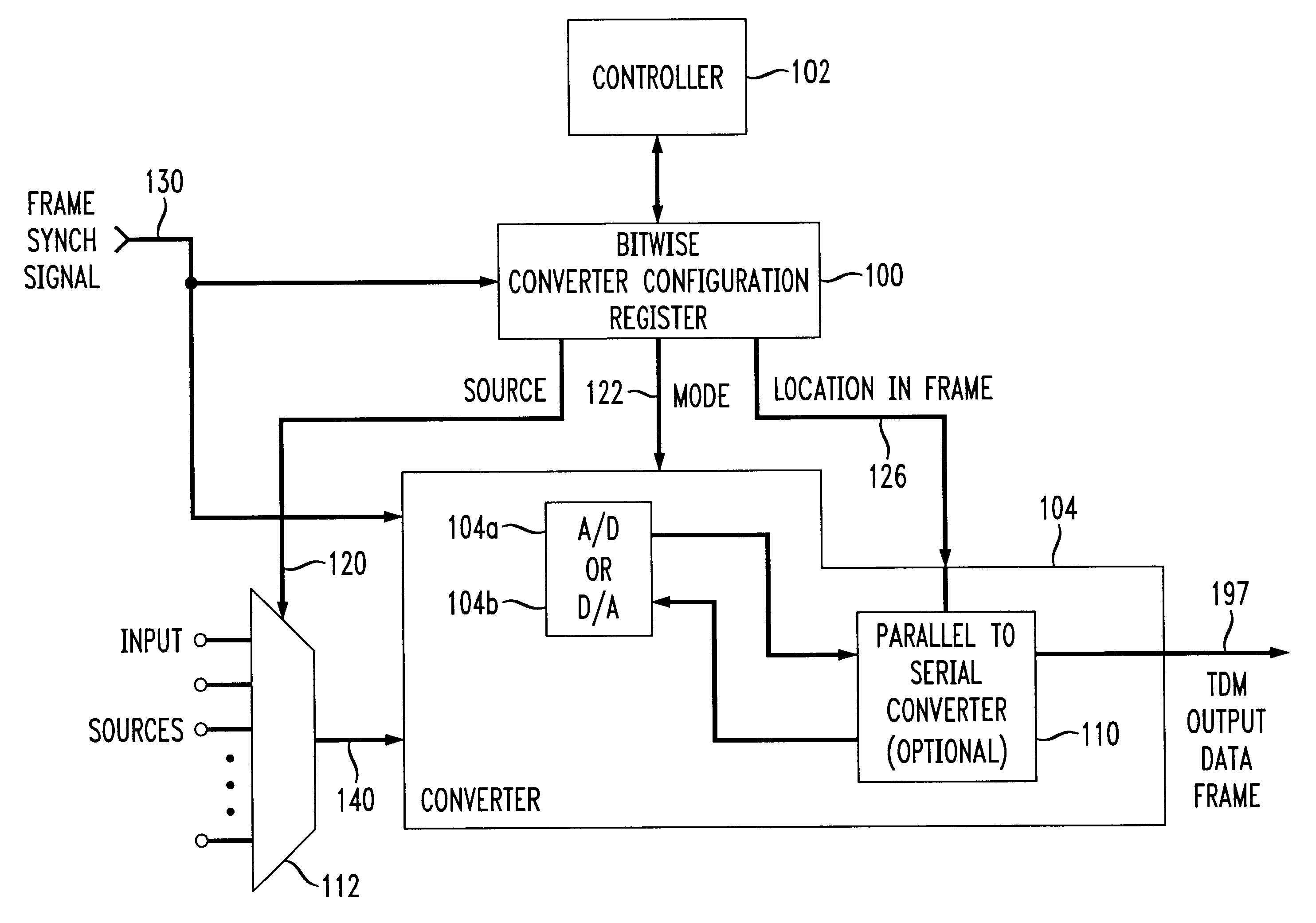
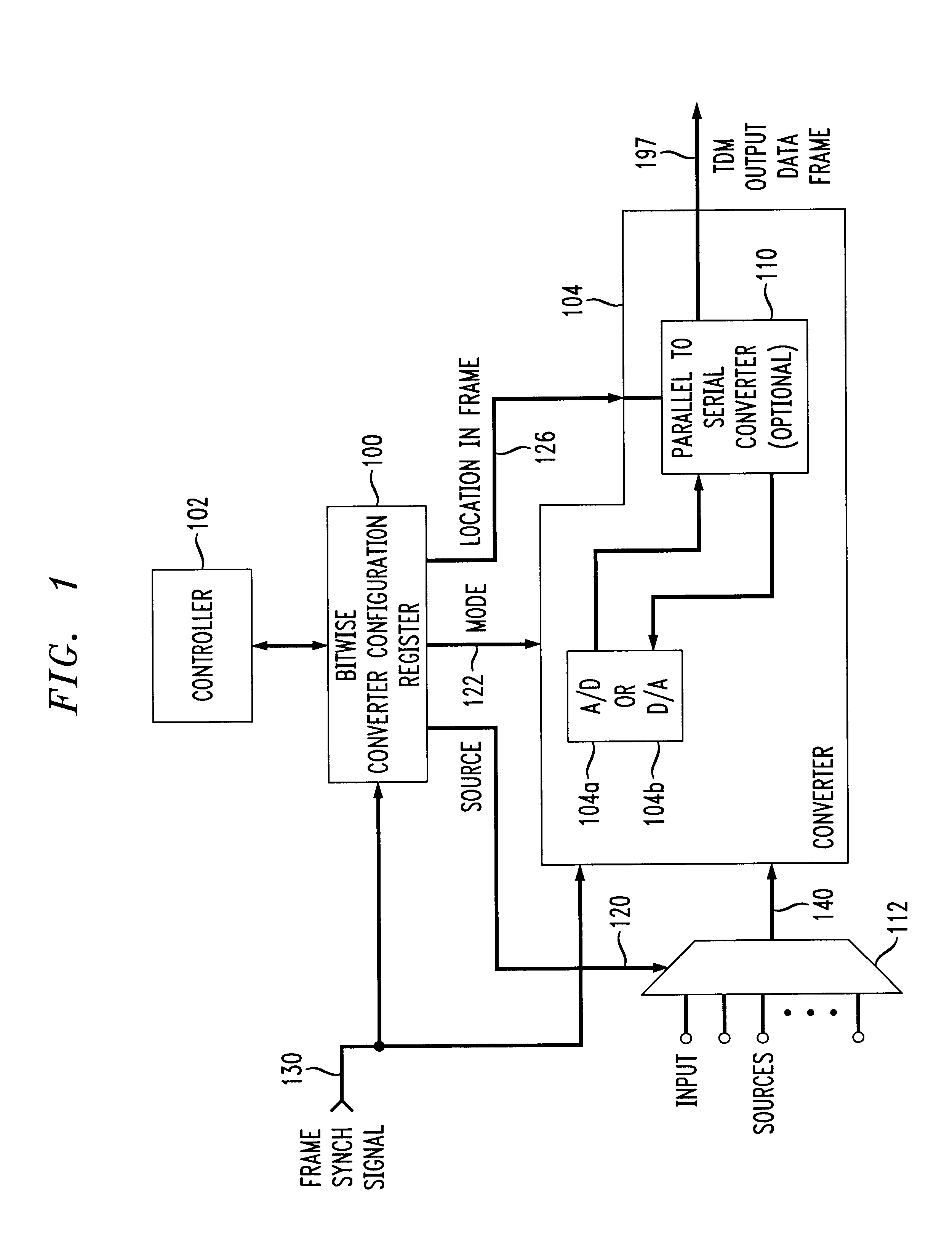
A / D converter or as a D / A converter forms a data converter embedded in a digital circuit for reconfigurable use. Conversion parameters of the data converter are controlled on a bitwise basis from a bitwise converter configuration register. For instance, output locations (i.e., time slots) of the data converter are determined by a bitwise converter configuration register, as is the selection of a D / A conversion mode or A / D conversion mode of the data converter for that particular output location, and / or the output sample length are controlled by appropriate signals from the bitwise converter configuration register. The bitwise converter configuration register also preferably configures the input source to the data converter and / or to an interface, e.g., to a parallel-to-serial, serial-to-serial, or parallel-to-parallel interface device, on a bitwise basis, to provide flexibility both in the source of the channels as well as the output location of particular channels in the data frame.
Description
1. Field of the InventionThe present invention relates generally to analog-to-digital (A / D) and digital-to-analog (D / A) converters. More particularly, it relates to an improved architecture design including a configurable embedded data converter.2. Background of Related ArtMany, many digital devices are utilized by consumers throughout the world. Many of these digital devices translate or convert an analog signal into a digital signal, and / or a digital signal back into an analog signal. For instance, compact disk (CD) players convert a digital signal read from a CD back into an analog signal for audible output by speakers. Moreover, telephone equipment such as digital cordless telephones and digital telephone answering devices convert between an analog signal (e.g., from a microphone) into a digital signal for digital transmission from a remote handset to a base unit (digital cordless telephone) or for digital storage in appropriate non-volatile memory (telephone answering device).E...
Claims
Login to View More Application Information
Patent Timeline
 IPC IPC(8): H03M1/00H03M1/02
CPCH03M1/02
InventorGROSS, JR., GEORGE F.HUGHES, GREGORY A.
OwnerLUCENT TECH INC