
Flat gasket ring

a gasket ring and gasket technology, applied in the direction of fluid pressure sealing joints, pipe elements, couplings, etc., can solve the problem that the gasket ring no longer covers the cross section of the sealing surfa

Inactive Publication Date: 2001-07-17
GEORG FISCHER ROHRLEITUNGSSYST
View PDF26 Cites 61 Cited by
  • Summary
  • Abstract
  • Description
  • Claims
  • Application Information

AI Technical Summary

Benefits of technology

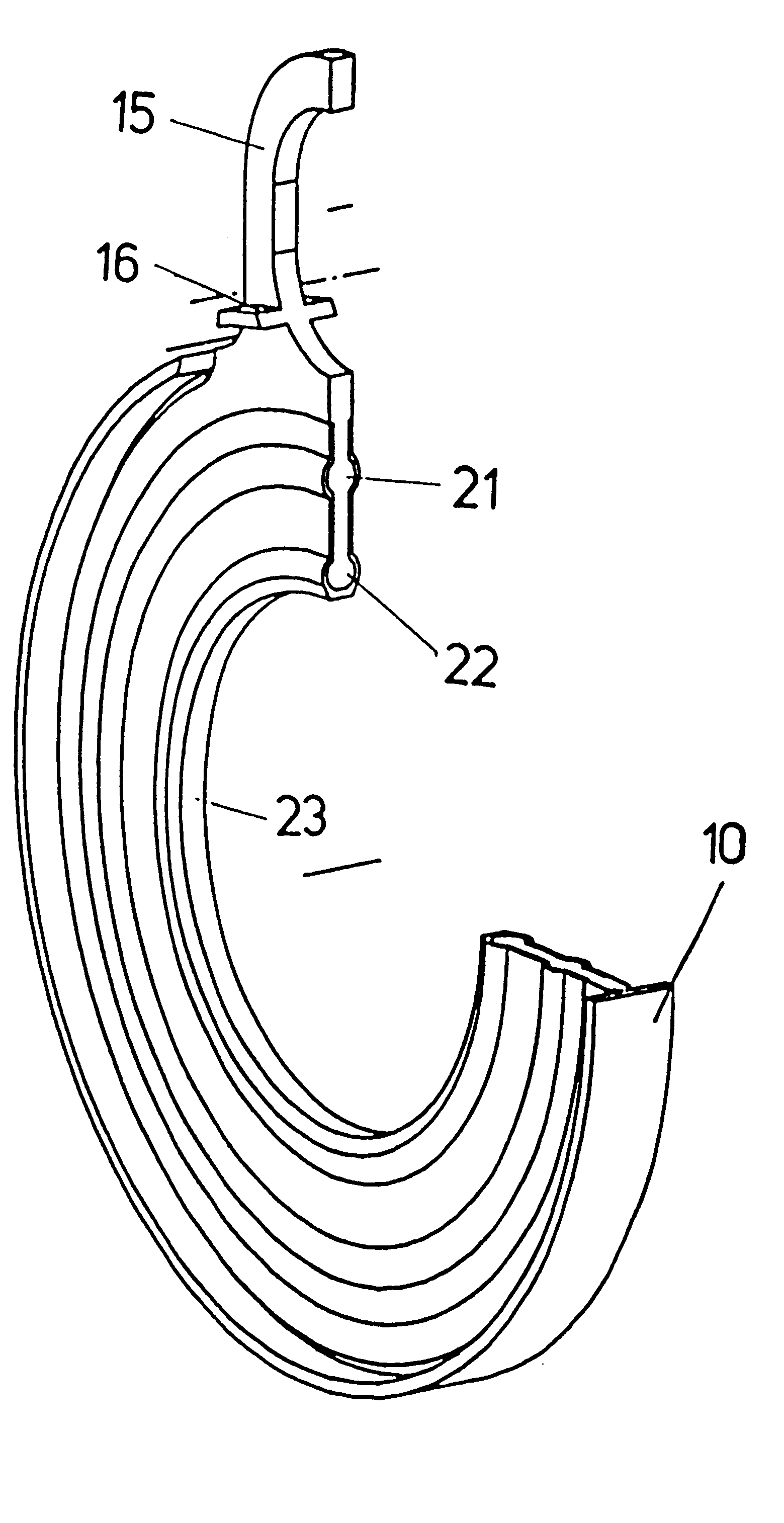
The flat gasket ring according to the invention is distinguished in that it has self-centering structural elements. By virtue of a lip which is provided concentrically on both sides of the external diameter of the flat gasket ring, the flat gasket ring can be applied accurately over the surface of a standard ANSI Sygef flange. This lip may be severed in order to position the flat gasket ring in ISO / DIN Sygef flanges of larger diameters than those of the ANSI standard.
A slot-like cutout is arranged in a lateral extension in the region of the second lip structure. As a result, the flat gasket ring can be retained by an assembly bolt or screw during installation, thus preventing the flat gasket ring from dropping out.

Problems solved by technology

Since the flange encloses the gasket ring, the latter is difficult to position, and inaccurate centering and slipping during installation may lead to the gasket ring no longer covering the cross section of the sealing surface.
This results in different pressures over the surface area in the sealing region, which in turn may result in leakage.
Such a transition has to be positively locking and smooth here, since uneven transitions cause turbulence in the flowing medium, which may have fluid-dynamic dead spaces.

Method used


Image

  • Flat gasket ring
  • Flat gasket ring
  • Flat gasket ring

Examples


Embodiment Construction

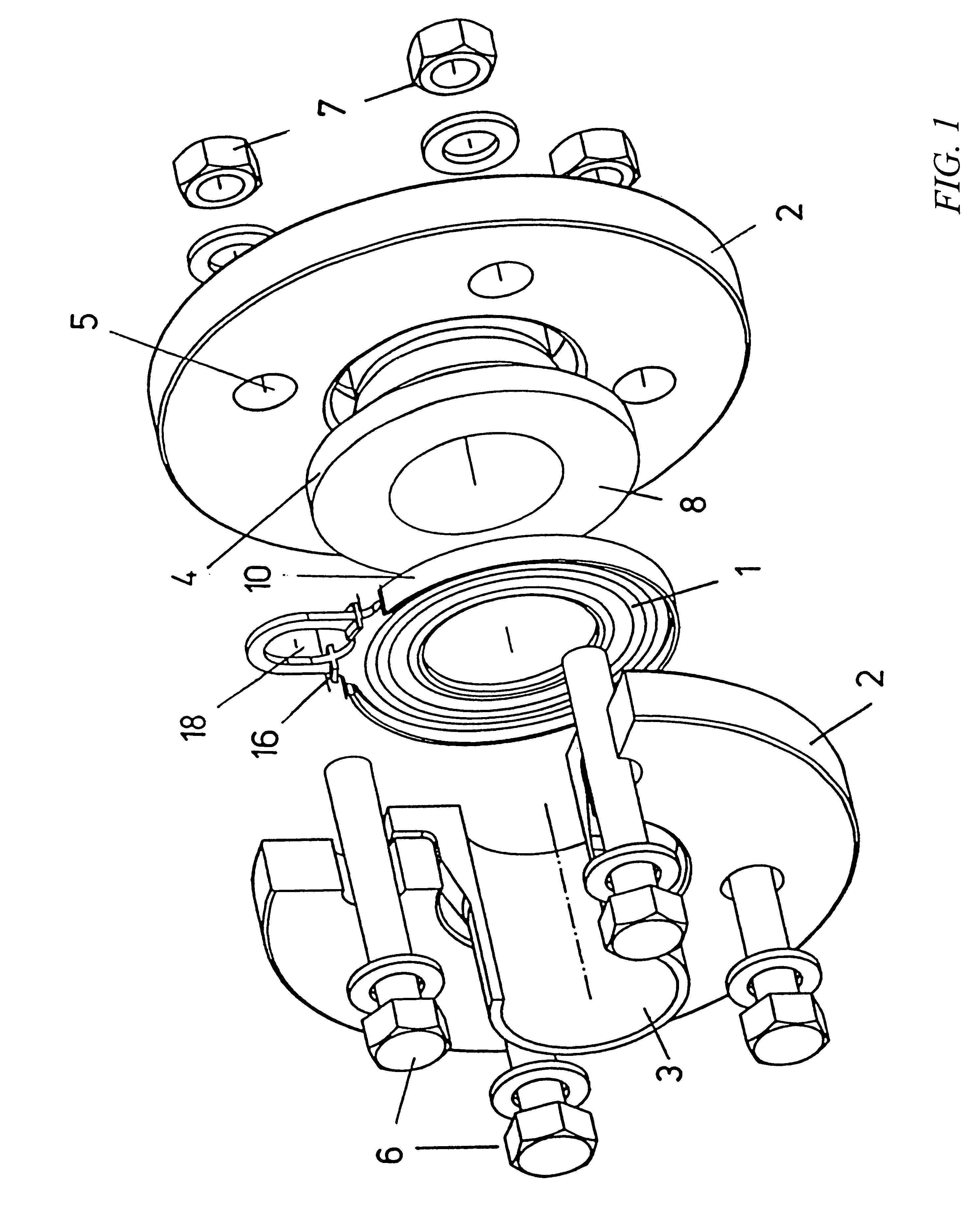
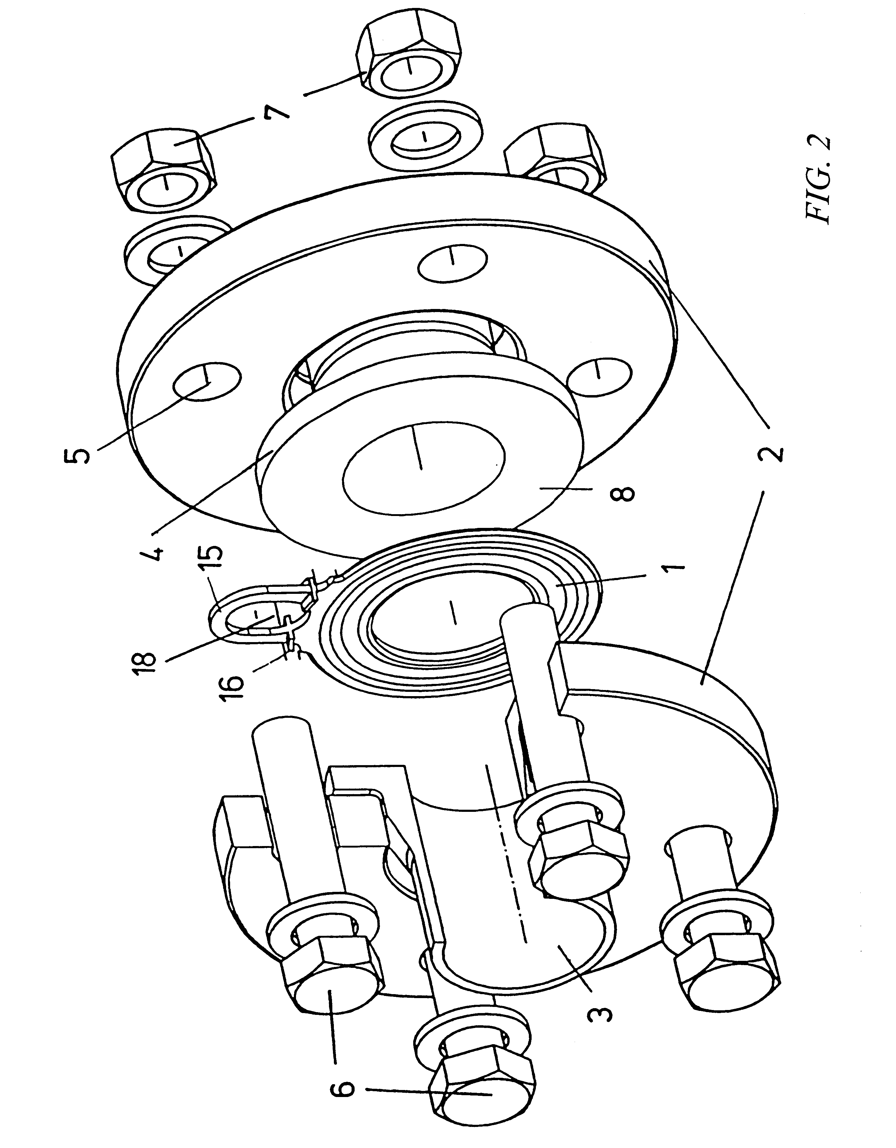
FIG. 1 shows, in a perspective illustration, the installation of the flat gasket ring 1 between two flange adapters in accordance with the ANSI standard. A flange 2 is pushed (with a small amount of play) in each case over a molding 3 provided with a collar 4, said flange having a plurality of symmetrically arranged openings 5 for receiving screwed connections 6. Screws 6 can be guided through respectively opposite openings 5 of the flanges 2, and the necessary contact pressure can be applied by tightening the associated nuts 7. In this case, the flat gasket ring 1, which is located between the sealing surfaces 8 of the collars 4, is compressed. The flat gasket ring is positioned in relation to the collar 4 by a lip 10, which butts against the external diameter of said collar 4. Since, as illustrated in FIG. 1, the flange 2 is pushed with play over the molding 3, there may be inaccuracies in the positioning in addition to those caused by tolerances of the openings 5 and screws 6 or ...


PUM

PropertyMeasurementUnit
Lengthaaaaaaaaaa
Thicknessaaaaaaaaaa
Diameteraaaaaaaaaa

Abstract

Flat gasket ring, in particular for producing a flange connection between moldings, the flat gasket ring having, along its outer circumferential line, lip structures which are intended for accommodating the gasket ring in a positively locking manner in relation to moldings.

Description

BACKGROUND OF THE INVENTIONThe present invention relates to a flat gasket ring, in particular for arranging between two flange adapters in pipeline systems.Transition connections are necessary when laying pipelines. These connections usually take place via moldings which are equipped with a flange adapter. In each case one flange is pushed over the molding which is to be connected, until said flange butts against a so-called welding collar. There are also moldings with an integrated flange. The sealing surfaces of the flange adapters of the two moldings which are to be connected to one another are brought into abutment with one another with the interposition of a flat gasket ring. The flanges are connected to one another by means of a plurality of screwed connections, in order for the seal, which is located between the sealing surfaces of the flange adapters, to be subjected to the contact pressure which is necessary for the fluid-tight connection. Flat gasket rings are used in the ...

Claims


Application Information

Patent Timeline
IPC IPC(8): F16J15/06F16L23/16
CPCF16J15/061F16L23/22Y10S277/917F16L2201/60
Inventor LEMON, BARRY
Owner GEORG FISCHER ROHRLEITUNGSSYST
Learn More