High-speed data receiving circuit and method

a data receiving circuit and high-speed technology, applied in the direction of digital transmission, pulse automatic control, electrical equipment, etc., can solve the problems of reducing the reliability of comparison, unable to capture correct data, and inability to capture correct data

Inactive Publication Date: 2001-07-17
NEC CORP
View PDF2 Cites 70 Cited by
  • Summary
  • Abstract
  • Description
  • Claims
  • Application Information

AI Technical Summary

Problems solved by technology

A combination of delays in these four routes may cause the reduced reliability of the comparison result obtained by the phase comparator 105.
This causes a problem such that correct data may not be captured.
Actually, since neither the setup time nor the hold time is satisfied, it is impossible to capture correct data.
However, there is a problem that, as the frequency of received data increases, the delays need to be adjusted so as to fall within a small range and therefore the circuit implementation becomes more difficult.

Method used


Image

  • High-speed data receiving circuit and method
  • High-speed data receiving circuit and method
  • High-speed data receiving circuit and method

Examples


Embodiment Construction

OF CLOCK SELECTOR

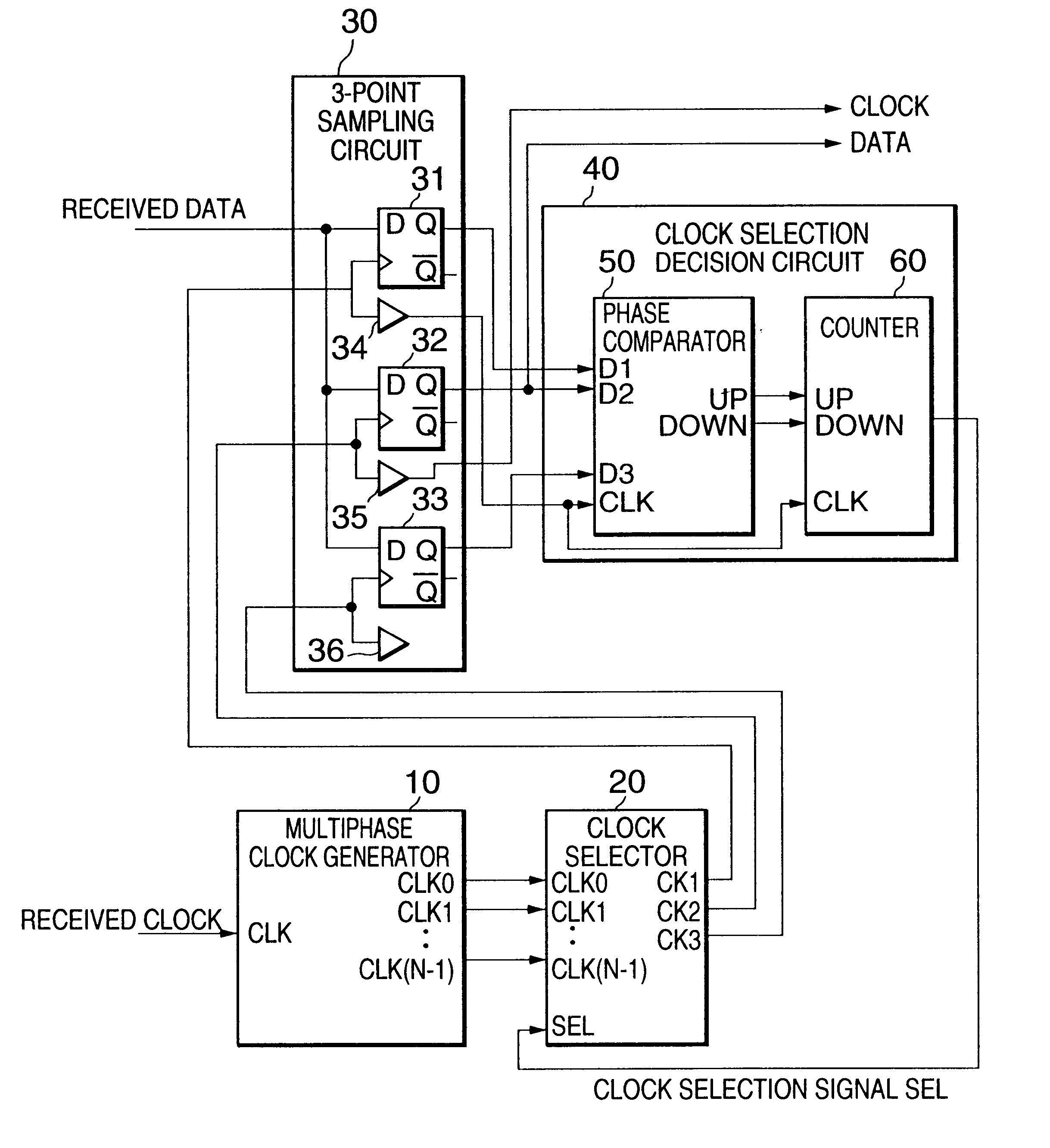
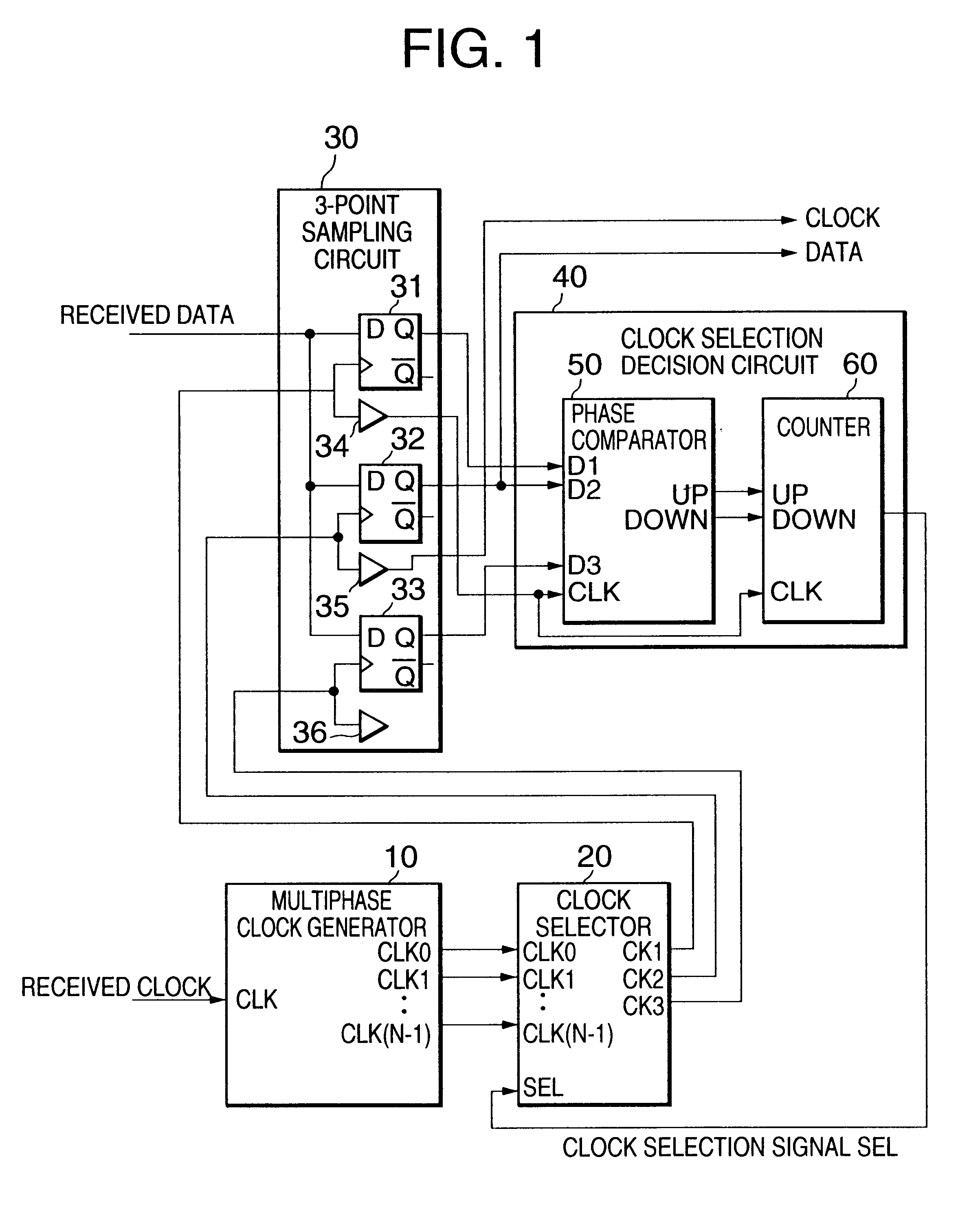
Referring to FIG. 6, the clock selector 20 may be formed from three selectors 24-26. Each of the selectors 24-26 receives multiphase clock signals CLK0 to CLK(N-1) from the multiphase clock generator 10 and a clock selection signal SEL from the clock selection decision circuit 40. A clock signal CLKk is received at the (k+2)-th input of the selector 24, the k-th input of the selector 25, and the (k-2)-th input of the selector 26. In the clock selector 20 having the above configuration, each of the selectors 24-26 selects one of the received clock signals CLK0 to CLK(N-1) in accordance with the clock selection signal SEL.

The selector 24 selects a clock signal CLK(SEL-2) from the clock signals CLK0 to CLK(N-1) and outputs it as a clock signal CLK1. The selector 25 selects a clock signal CLK(SEL) from the clock signals CLK0 to CLK(N-1) and outputs it as a clock signal CL2. The selector 26 selects a clock signal CLK(SEL+2) from the clock signals CLK0 to CLK(N-1) and out...


PUM


Abstract

A high-speed data receiving circuit allowing correct and reliable data reception without the need for adjusting delays in circuits and interconnections is disclosed. A sampling circuit samples received data according to first, second, and third clock signals to produce first, second, and third streams of data. The first, second, and third clock signals sequentially have a predetermined phase difference between adjacent ones. A clock generator generates the first, second, and third clock signals having phases determined depending on a clock selection signal obtained by comparing the first, second, and third streams of data. The second clock signal is selected as an output clock signal and the second stream of data corresponding to said second clock signal is selected as an output data of the high-speed data receiving circuit.

Description

1. Field of the InventionThe present invention relates to data receiving techniques in a high-speed data transmission system. In particular, the invention relates to a high-speed data receiving circuit and method allowing reliable data reception even when a received clock signal and / or the received data vary in phase.2. Description of the Prior ArtIn Japanese Patent Application Unexamined Publication No. 10-247903, a bit-sync circuit has been disclosed in which the phase of received data is compared with the phases of multiple clock signals generated from a system clock signal and a clock signal having a phase to be used for data capturing is selected from the multiple clock signals depending on a comparison result.More specifically, the above conventional circuit in the case of 4-phase clock signals as describe din the Publication No. 10-247903 will be described referring to FIG. 8.As shown in FIG. 8, this conventional example is composed of the following circuits. Delay circuits 1...

Claims


Application Information

Patent Timeline
Patent Type & Authority Patents(United States)
IPC IPC(8): H04L7/033
CPCH04L7/0337
Inventor TAKEUCHI, MASAHIRO
Owner NEC CORP
Why Eureka
Try Eureka