

One-chip microcomputer system
a microcomputer and one-chip technology, applied in the field of one-chip microcomputer systems, can solve the problems of high-brightness led, expensive and difficult to obtain, and achieve the effect of improving the accuracy of the led
- Summary
- Abstract
- Description
- Claims
- Application Information
AI Technical Summary
Problems solved by technology
Method used
Image

Examples
embodiment 1
A one-chip microcomputer system of Embodiment 1 of the present invention will be described with reference FIGS. 1A, 1B, and 2 to 4.
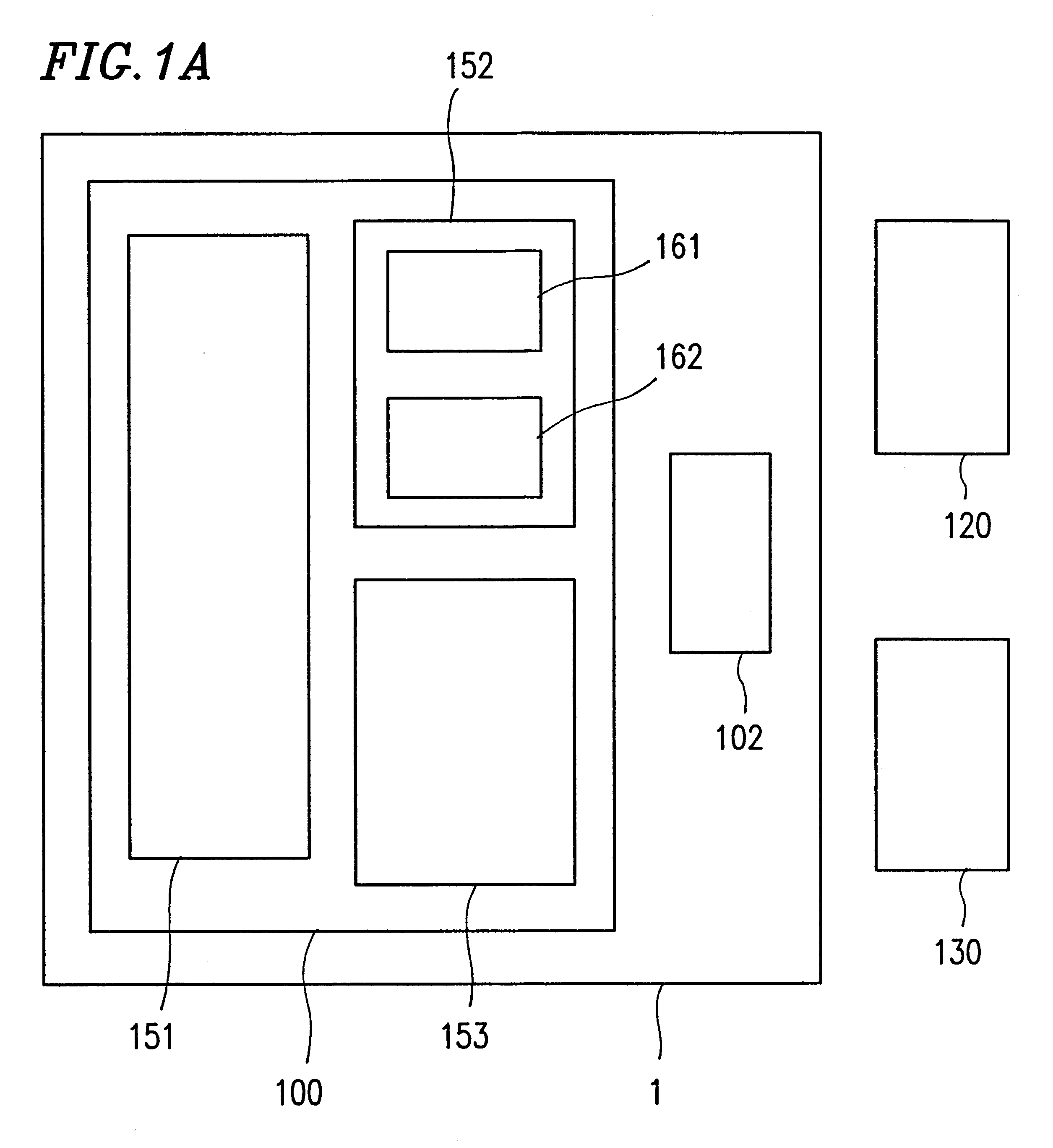
FIG. 1A shows an example of the one-chip microcomputer system of Embodiment 1.
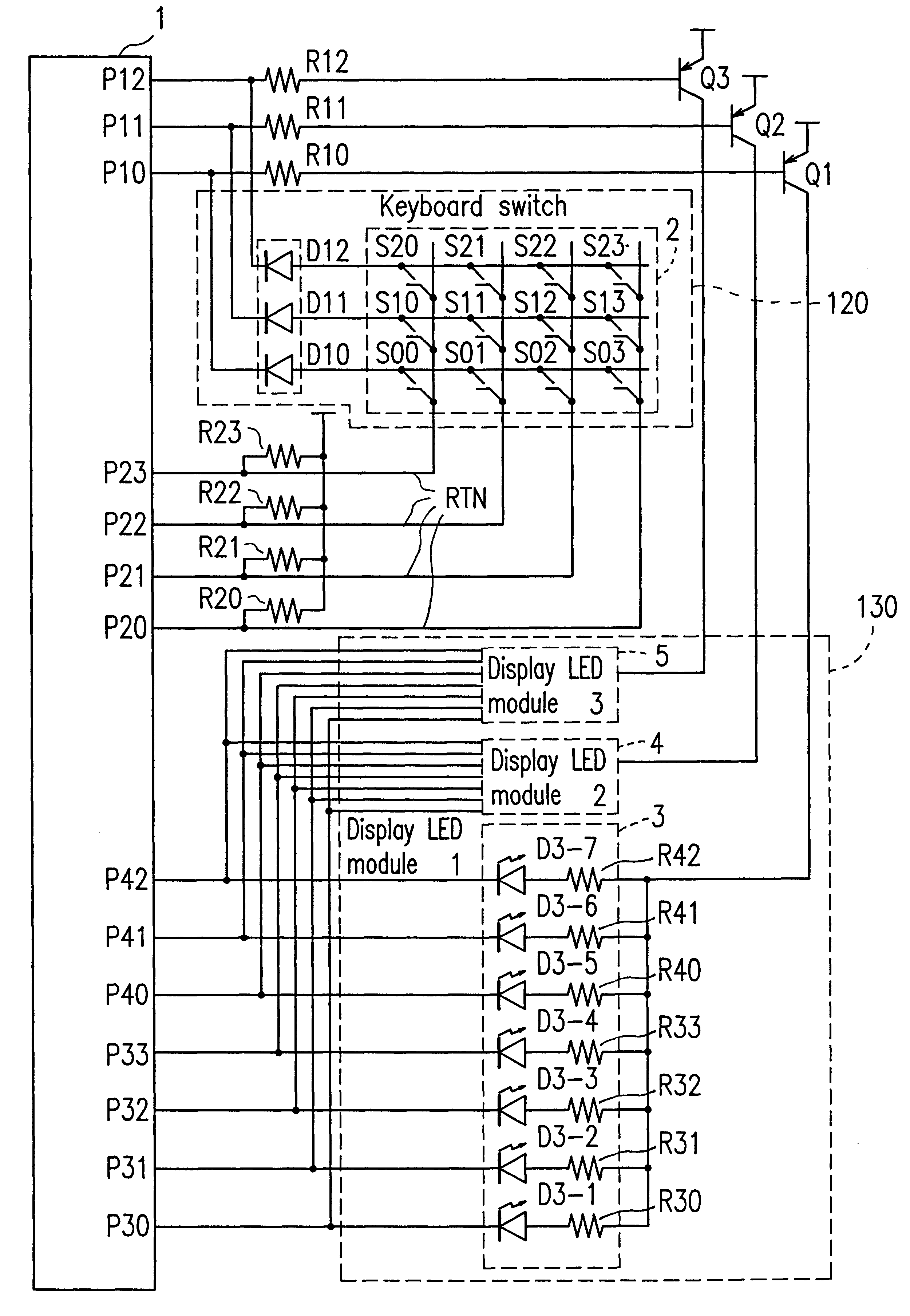
The one-chip microcomputer system of Embodiment 1 shown in FIG. 1A includes a microcomputer 1, a keyboard switch 120, and a display device 130 such as a 7-segment LED and a fluorescent display tube. The microcomputer 1 includes a CPU 100 and a common port 102 for scanning the keyboard switch 120 and controlling the display device 130. The CPU 100 uses the common port 102 and other ports (not shown) to scan the key switch 120 and control the display device 130. Furthermore, the CPU 100 determines which key is specified by the keyboard switch 120, based on the results of scanning.
In order to perform the above-mentioned operation, the CPU 100 includes a display driving circuit 152 for driving the display device 130, a scanning circuit 153 for scanning the keyboard switch 120, and ...
embodiment 2
A one-chip microcomputer system of Embodiment 2 of the present invention will be described with reference to FIGS. 5 to 7. In the one-chip microcomputer system of Embodiment 2, a display is driven in time division on a-segment basis or on a digit basis.
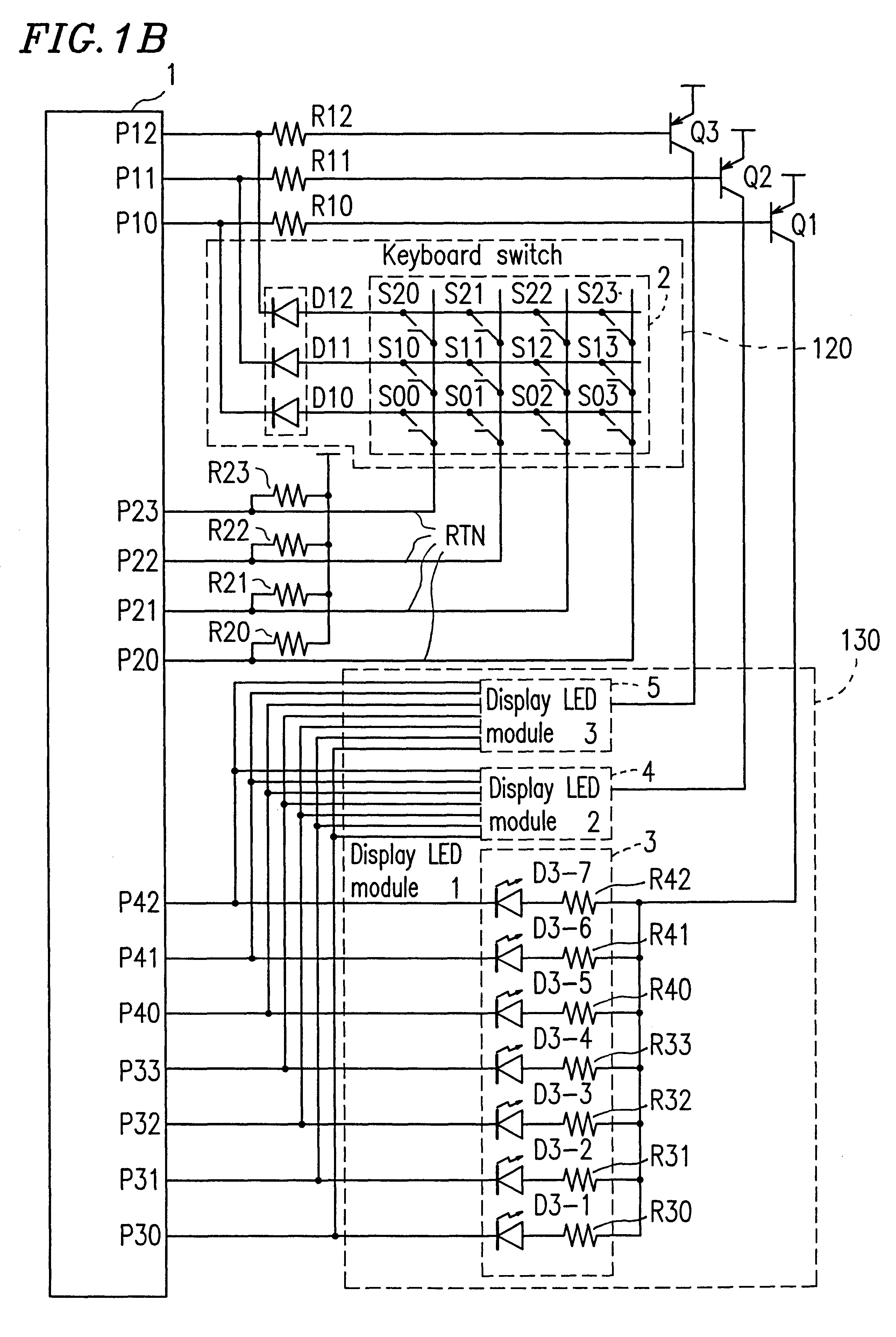
FIG. 5 shows a circuit configuration of the one-chip microcomputer system of Embodiment 2 which is different from that of the one-chip microcomputer system of Embodiment 1 shown in FIG. 1 in that an additional segment driving port P43 connected to a power source is used in Embodiment 2.
Furthermore, the CPU 200 is different from the CPU 100 in a program for controlling a procedure of a display and scanning a keyboard switch. The details of the program will be described later. In FIG. 5, the components identical with those in FIG. 1 are denoted by the reference numerals identical with those therein.
Next, an operation timing of the one-chip microcomputer system of Embodiment 2 will be described with reference to FIG. 6.
In FIG. 6, the CPU...
embodiment 3
A one-chip microcomputer system of Embodiment 3 of the present invention will be described with reference to FIGS. 8A, 8B, and 9 to 11. The one-chip microcomputer system of Embodiment 3 has a structure in which a display control unit (DSPC) 11-12 shown in FIG. 8B is incorporated into a microcomputer 11 shown in FIG. 8A.
First, an internal structure of the microcomputer 11 will be described with reference to FIG. 8A. The microcomputer 11 includes a CPU 300, Port 1 (11-2), Port 2 (11-3), Port 3 (11-4) and Port 4 (11-5), a timer unit 11-6, a RAM 11-7, a ROM 11-8, a clock generator (CG) 11-9, an internal data bus line 11-10, and a control bus line 11-11, This structure is the same as that of the microcomputer 1 shown in FIG. 2.
In addition to the above-mentioned structure, the microcomputer 11 includes the above-mentioned display control unit 11-12, multiplexers 11-13, 11-14, and 11-15, and a counter 11-16 for measuring a period Tf.
The multiplexer 11-13 multiplexes outputs from the displa...
PUM
 Abstract
Description
Claims
Application Information