
Self advancing mining sled

Inactive Publication Date: 2001-07-31
ROTHSCHILD KEITH R
View PDF7 Cites 18 Cited by
  • Summary
  • Abstract
  • Description
  • Claims
  • Application Information

AI Technical Summary

Benefits of technology

Thus, the described invention provides a reliable, economical, and self-contained means to transport heavy equipment units across all types of surfaces that may vary from very hard to very soft conditions. The described equipment has provision to achieve vertical curves to fit undulating surfaces and has

Problems solved by technology

Continued operation causes the distance between the bulk solids and the handling system to increase until continued operation is either impossible or unacceptably inefficient.
While the crawler system described above provides great operational flexibility, it also suffers from two disadvantages.
Firstly, the crawler system is a complex machinery unit with multiple moving parts that are expensive to manufacture and to maintain.
Secondly, the crawler system has limited bearing surface over which to distribute the weight of the crawler and bulk handling equipment.
This means that crawler systems cannot economically operate on surfaces with low bearing strength such as that found in wet or clayey soils.
While the width and length of the crawlers may be increased to provide greater bearing surface, the cost of manufacture and operation increases accordingly.
Thus, it is seen that crawler systems are limited to working on surfaces with good bearing strength and where the need for a highly mobile operation overcomes the disadvantage of high costs.
Wheel mounted systems provide very small bearing surface over which to distribute the equipment weight and are therefore limited to working on surfaces with very good bearing strength.
However, these units have no self-propulsion mechanism and must be drug or pushed into position by wheeled or tracked equipment described previously.
Thus, this method of equipment relocation is limited to situations where relocation is infrequent.
None of the existing means for relocating bulk solids handling equipment address the situation where the equipment is required to frequently or continuously travel across surfaces with very low bearing support unless the equipment is operating within a confined space such as a trench or underground mine.

Method used


Image

  • Self advancing mining sled
  • Self advancing mining sled
  • Self advancing mining sled

Examples


Embodiment Construction

. 1 THROUGH 4

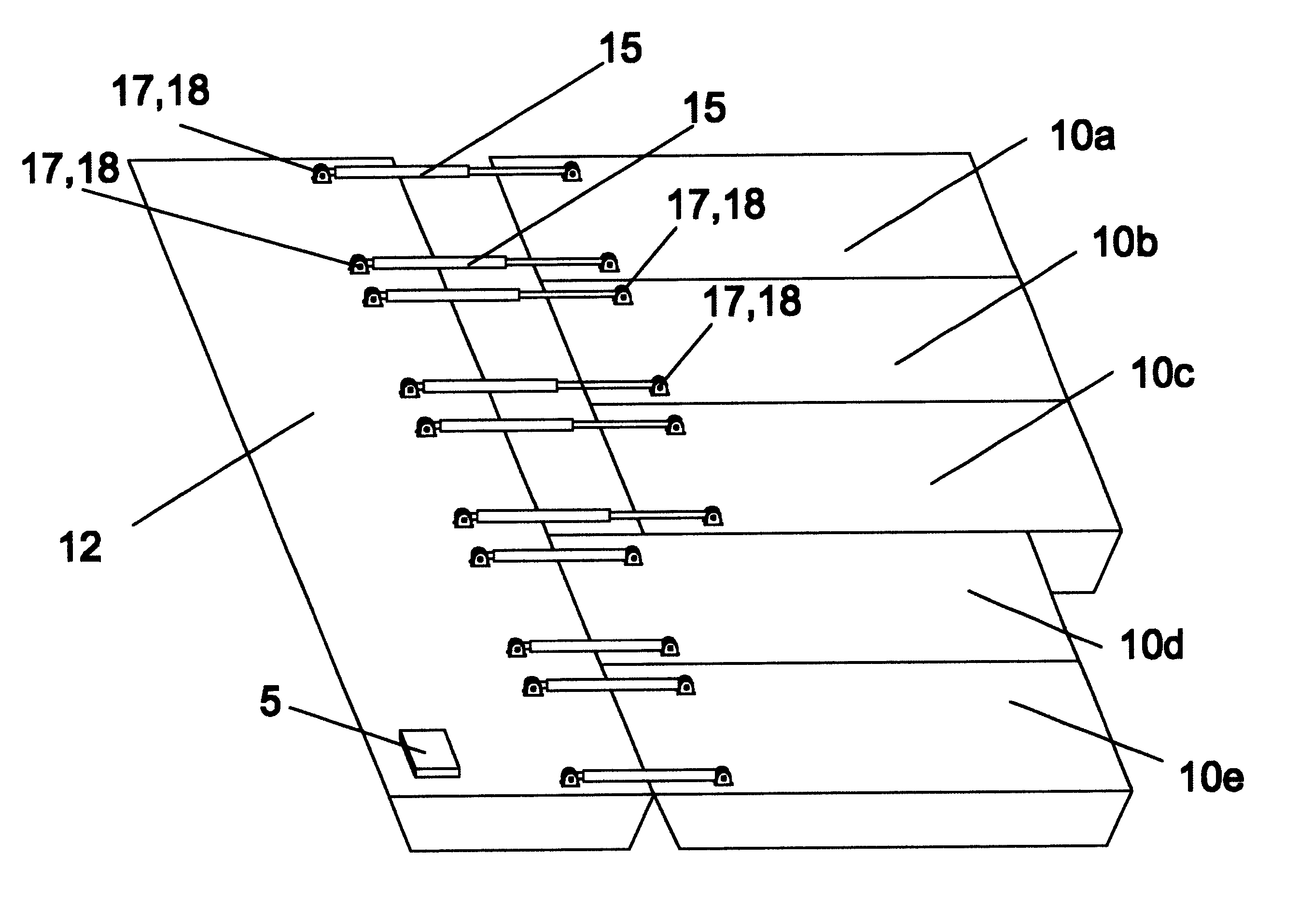
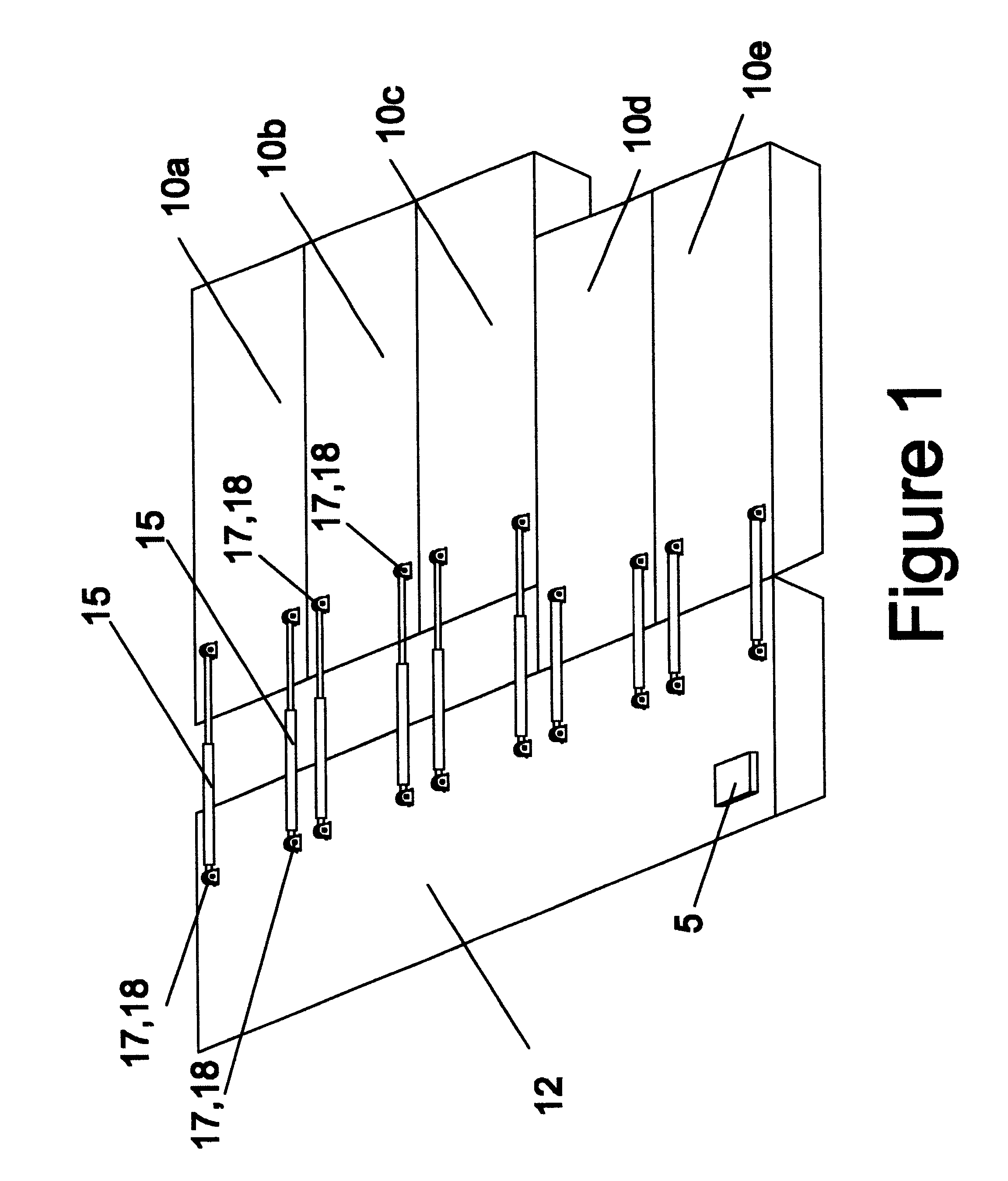
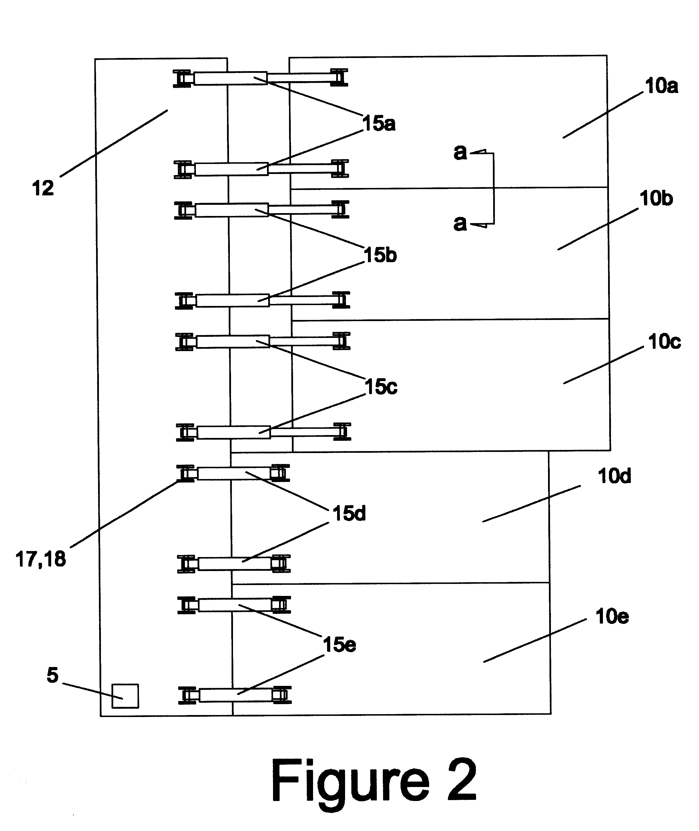
A typical embodiment of the Self Advancing Mining Sled is shown in isometric view in FIG. 1, in plan view in FIG. 2, and in side view in FIG. 3. The Self Advancing Mining Sled as shown is comprised of five Advancing Sleds 10 and one Equipment Base Sled 12. Any combination of Advancing Sleds 10 and Equipment Base Sleds 12 may be used, in accordance with principles described below.

FIGS. 1, 2, and 3 indicate Advancing Sleds 10 and Equipment Base Sled 12 as rectangular box-like structures with angled leading and trailing edges. Any other shape can be used with the provision of sufficient bearing surface to support the weight of the Self Advancing Mining Sled and equipment transported there on. These structures may be constructed of steel, aluminum, wood, plastic, or any other fabrication material. Advancing Sleds 10 and Equipment Base Sled 12 will be structurally designed according to known design art and the requirement of the equipment to be carried on the Self Advancing ...


PUM


Abstract

Disclosed is a self propelled device and method for transporting and positioning bulk solids handling equipment across working surfaces of limited bearing strength. Multiple advancing sleds (10) and equipment base sleds (12) are connected by interlocking angles (21) and thrust cylinders (15). Alternate extension and retraction of thrust cylinders (15) cause alternate sleds to push forward while other sleds serve as anchors. Methods to use the self advancing mining sled in hydraulic mining and dry mining applications are disclosed.

Description

1. Field of the InventionThis invention relates in general to the field of mining and, in particular, to a novel method to relocate and position bulk solids handling machinery used in surface mining activities.2. Description of Prior ArtBulk solids handling machinery such as slurry sluicing systems, conveyor belt systems, drag conveyor systems, crushers, grinders, screens, centrifuges, cyclones and other equipment and systems, are used to transport or treat material such as ore, farm products, wood chips, and other bulk solid materials, These systems may be used to move these bulk materials from stockpiles, settling ponds, spill collection areas, mining or agricultural operations and other situations.In many cases, operation of these systems requires the systems to be periodically relocated. Material close to and within reach of the system is gathered and transported by the system. Continued operation causes the distance between the bulk solids and the handling system to increase un...

Claims


Application Information

Patent Timeline
IPC IPC(8): B62D57/00B62D57/032E02F9/02E02F9/04E02F9/00E02F1/00
CPCB62D57/032E02F9/04E02F9/003E02F1/00
Inventor HETTINGER, DAVID ALLYN
Owner ROTHSCHILD KEITH R
Learn More