Image flicker reduction with fluorescent lighting

a technology of fluorescent lighting and flicker reduction, applied in the field of digital imaging systems, can solve problems such as flicker in digital imagers in particular

Inactive Publication Date: 2001-08-07
ESS TECH INT INC +1
View PDF7 Cites 68 Cited by
  • Summary
  • Abstract
  • Description
  • Claims
  • Application Information

AI Technical Summary

Problems solved by technology

One problem pertaining to imaging systems generally and to digital imagers in particular is that of flicker.
But when such a frame rate is

Method used


Image

  • Image flicker reduction with fluorescent lighting
  • Image flicker reduction with fluorescent lighting
  • Image flicker reduction with fluorescent lighting

Examples


Embodiment Construction

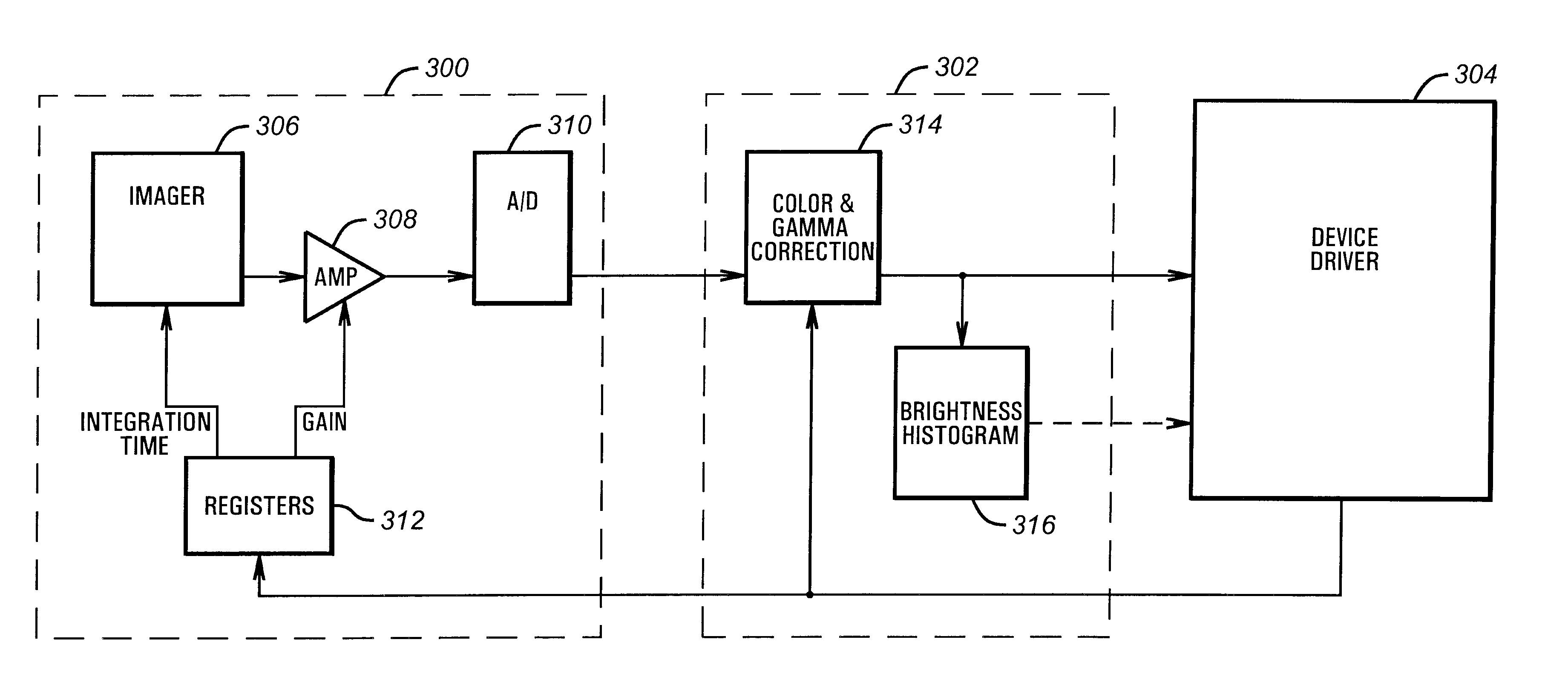
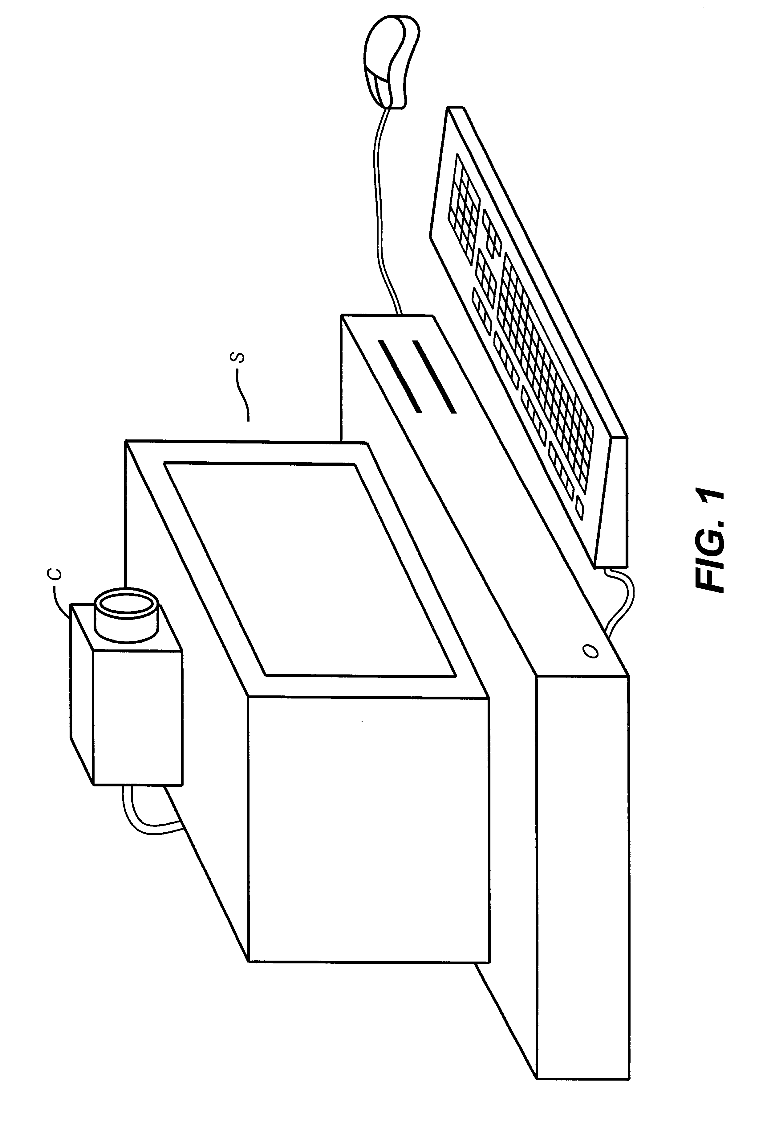
Turning to FIG. 1, illustrated is a typical digital video camera C coupled to a general purpose computer system S in which features of the invention are implemented. The video camera C is preferably coupled to a computer system S via a Universal Serial Bus (USB), and together this system employs flicker reduction according to the invention. The system illustrated in FIG. 1 preferably employs a device driver on the computer system S that controls the functions of the video camera C. Further details of this system are described below in conjunction with FIG. 4.

This system is particularly useful for videoconferencing, such as over the Internet. In particular, the video camera C preferably employs a 30 Hz image capture rate, which is compatible with the requirements of the ITU-T recommendation H.324 specification for terminals for low bit-rate multimedia communications. When a 30 Hz image capture rate is employed in the system of FIG. 1 in an environment in which 50 Hz fluorescent light...


PUM


Abstract

An imager reduces lighting induced flicker by setting its pixel integration time to an integral multiple of the periods between peak intensity of the lighting. In one implementation, flicker is reduced in a 30 Hz frame rate camera capturing an image lighted with 50 Hz lighting by setting the integration time to approximately 10 ms, the period between lighting intensity peaks.

Description

1. Field of the InventionThe invention pertains to digital imaging systems, and more particularly to a digital imaging system with reduced flicker caused by fluorescent lighting.2. Description of the Related ArtDigital imagers have become commonplace in the last decade. For both video cameras and still cameras, semiconductor devices are commonly used to capture an image on a pixel-by-pixel basis and electronically process that image. Such devices as charge coupled devices (CCDs) and CMOS digital imagers have resulted in low cost video cameras, still cameras, and more recently cameras for coupling to computer systems for video conferencing and other image capture.One problem pertaining to imaging systems generally and to digital imagers in particular is that of flicker. Flicker can arise from many sources, but in capturing digital video flicker especially results from a relationship between some periodic phenomena and the frame rate of the camera. Digital video cameras capture images...

Claims


Application Information

Patent Timeline
IPC IPC(8): H04N9/73H04N5/235H04N5/243H04N101/00
CPCH04N9/73H04N5/235H04N23/70
Inventor CHUNG, RANDALL M.BISHAY, MAGUED M.PINE, JOSHUA IAN
Owner ESS TECH INT INC
Why Eureka
Try Eureka