Switch structure

a technology of switch structure and switch, which is applied in the direction of circuit-breaking switches, relays, protective switch terminals/connections, etc., can solve the problems of affecting the safety of users, etc., and achieves simple structure, short response time, and slow response time

Inactive Publication Date: 2001-08-14
YU TSUNG MOU
View PDF22 Cites 17 Cited by
  • Summary
  • Abstract
  • Description
  • Claims
  • Application Information

AI Technical Summary

Benefits of technology

, those improved power switches in the prior arts can partly overcome the danger of overheating for the appliance but the response is slow and the whole structure is complicated. An advanced power switch with simpler structure and a short response time is greatly desired.

Problems solved by technology

However, it is risky to use the above power switches when the power source is unstable because overheating may occur due to overloading of the appliance and the wires easily catche the fire.
The users can not be aware of such latent danger since overloading and overheating are invisible.
Thermal deformation of the alloy piece causes the lever to move, and then the cam actuator loses support, escapes and further cuts off the power source.
Overheating may occur on he alloy piece.
The response of the power off operation in the above power switch when overheating occurs is so slow that the overloaded current may flow into the operating appliance in a short time to damage the appliance.
Additionally, the conductive plate and the alloy piece need the wire to connect to each other, and the whole structure is complicated to cause the manufacturing to be difficult.
The function of automatic power off may incorrectly operate.
The whole structure is still complicated.
In summary, those improved power switches in the prior arts can partly overcome the danger of overheating for the appliance but the response is slow and the whole structure is complicated.

Method used


Image

  • Switch structure
  • Switch structure
  • Switch structure

Examples


Embodiment Construction

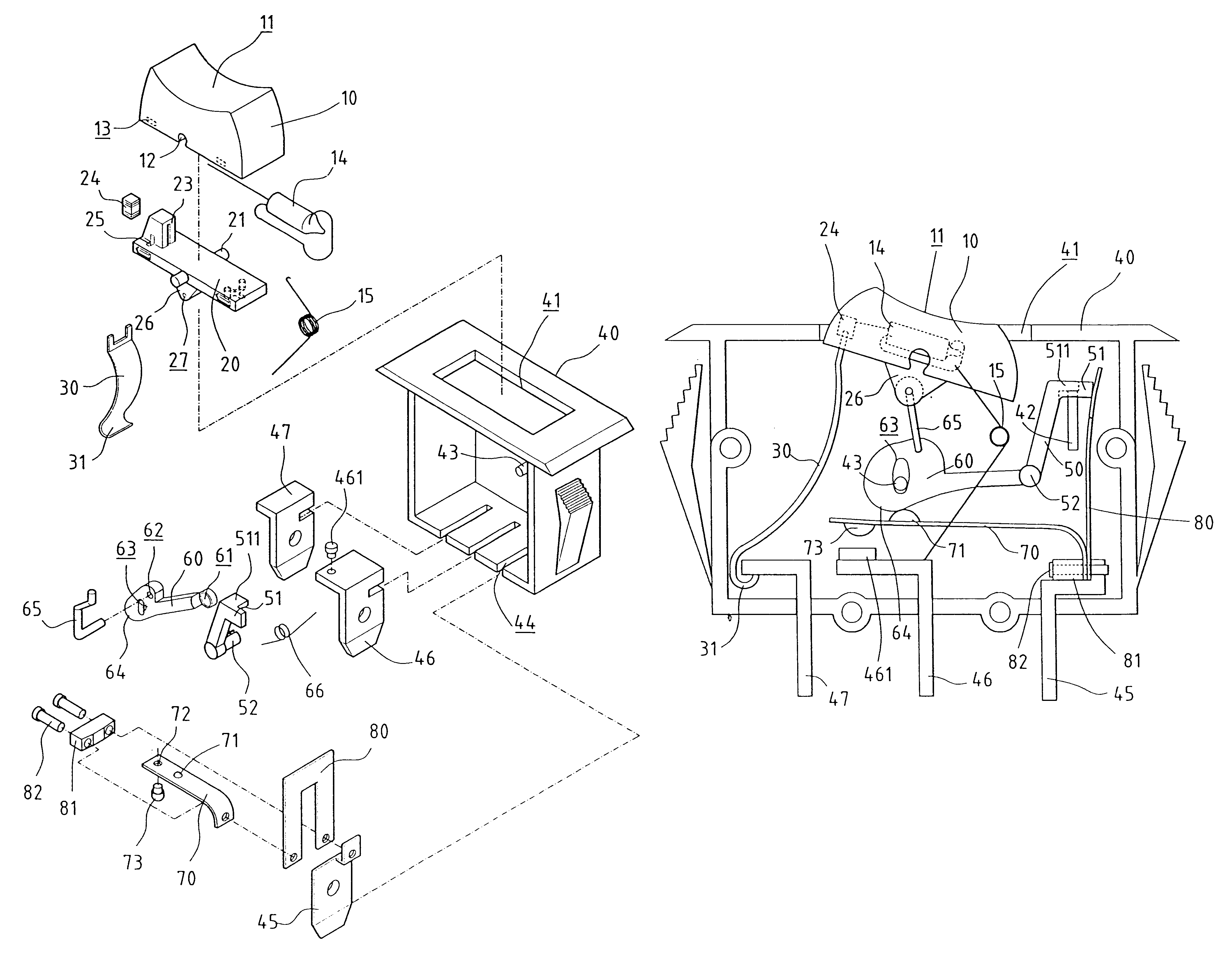
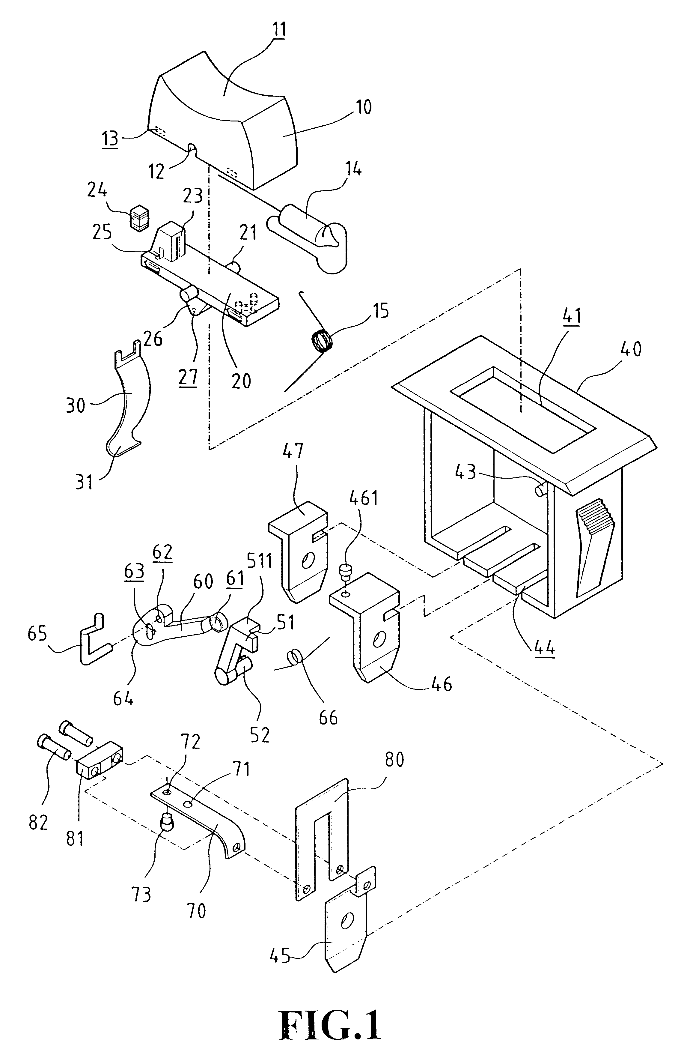
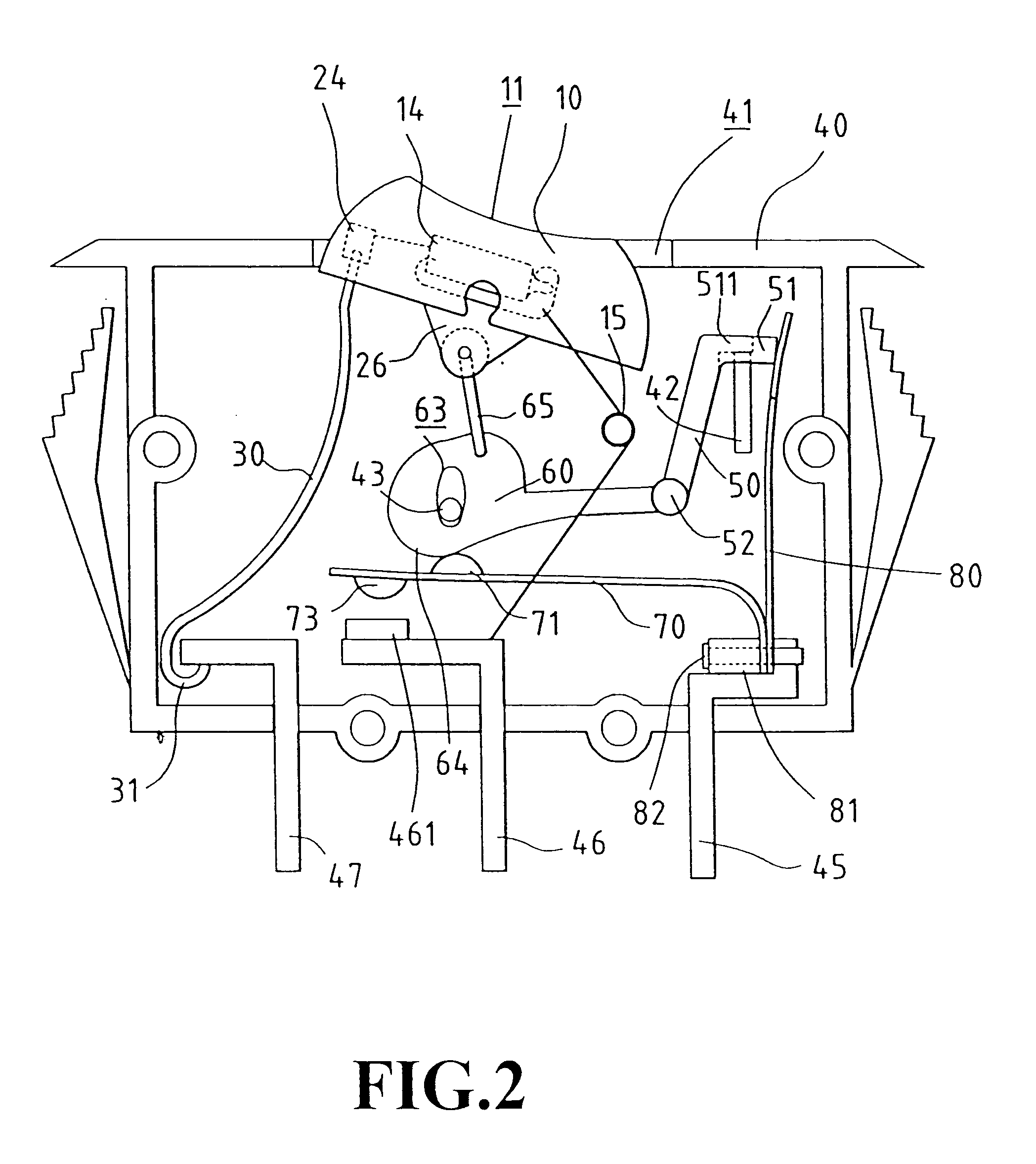
With reference to FIG. 1, the switch structure comprises a switch cover body 10, a contact reed 30, a switch body 40, a swing device 60, an elastic contact piece 70, and an alloy piece 80.

The switch cover body 10 includes a switch seat 20. The upper surface of the switch cover body 10 forms a concave cambered surface 11. Axial holes 12 and buckle holes 13 are formed at the proper positions at the two sides thereof. In the switch seat 20, two fulcrums 21 and two tenons 22 are installed at positions with respect to the axial holes 12 and buckle holes 13 of the switch cover body 10 to join the switch cover body 10, which presses in two directions along the fulcrums 21. A resistor seat 23 is formed at one side of the switch seat 20. A chip resistor 24 is embedded into the resistor seat 23 as a current limiting resistor of the neon lamp 14 within the switch cover body 10 for indicating that the switch is ON. Each side of the resistor seat 23 is installed with a through hole 25. The botto...


PUM


Abstract

A switch structure comprises a control element, which comprises an alloy piece and a swinging device. The swinging device has an actuating element used to actuate the swinging device when the actuating element is pushed. When the alloy piece is overheated due to overloading of current, it will deform toward the actuating element so as to eject the actuating element, which causes the swing device to swing outwards and is released from the supporting of the stopper in the switch body. Then, the swing device moves towards the original closing position, and the elastic contacting piece is released from the pressing of the swing device to eject upwards. Two joints connected in an electric loop are tripped. The object of rapid response, cutting power source, and safety is therefore achieved.

Description

FIELD OF THE INVENTIONThe present invention relates to a switch structure, and more specifically, to a power switch with a simpler structure that is capable of switching off the power source when the current is overloaded.BACKGROUND OF THE INVENTIONPower switches with only two states of ON and OFF functions controlled manually have been widely used in many appliances. However, it is risky to use the above power switches when the power source is unstable because overheating may occur due to overloading of the appliance and the wires easily catche the fire. The users can not be aware of such latent danger since overloading and overheating are invisible. Therefore, such improved power switches have been greatly needed to overcome the danger.Some improved power switch of the prior arts includes an alloy element composed of more than one metal to automatically shut off the power source when the alloy element is thermally deformed because of overheating.For example, the power switch discl...

Claims


Application Information

Patent Timeline
Patent Type & Authority Patents(United States)
IPC IPC(8): H01H73/26H01H73/00
CPCH01H73/26
Inventor CHEN, CHUN-HSU
Owner YU TSUNG MOU
Why Eureka
Try Eureka