Engine layout for outboard motor

a technology for outboard motors and components, applied in mechanical equipment, machines/engines, casings, etc., can solve the problems of occupying a relatively large space, increasing the size of the engine, and taking a long time for the lubricant to travel down the sides of the crank chamber

Inactive Publication Date: 2001-08-21
SANSHIN KOGYO CO LTD
View PDF10 Cites 22 Cited by
  • Summary
  • Abstract
  • Description
  • Claims
  • Application Information

AI Technical Summary

Problems solved by technology

Because both of these systems are positioned on the same side of the engine, they occupy a relatively large space.
This increases the size of the engine.
A problem with this arrangement is that it typically takes a long time for the lubricant to travel

Method used


Image

  • Engine layout for outboard motor
  • Engine layout for outboard motor
  • Engine layout for outboard motor

Examples


Embodiment Construction

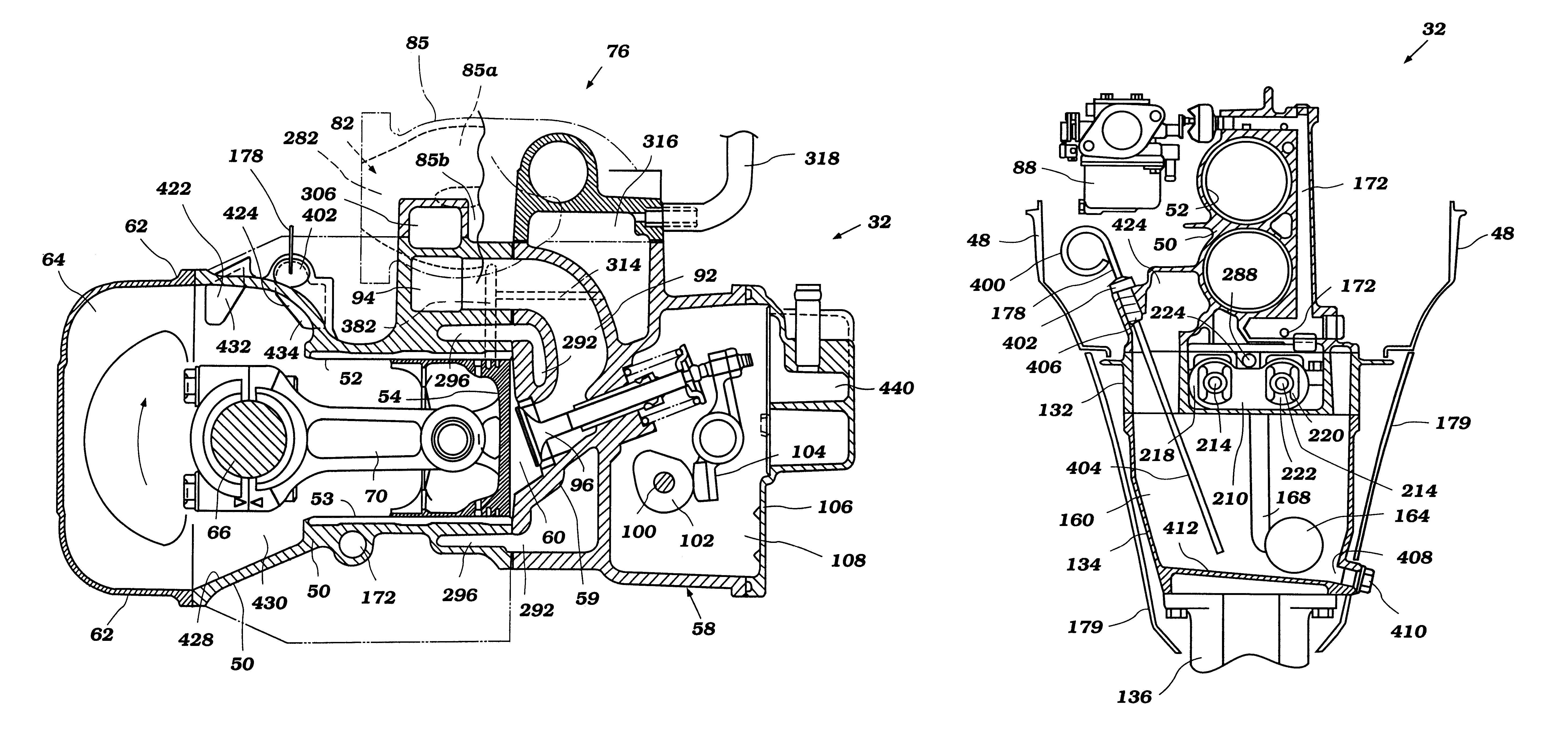
The present invention generally relates to an improved arrangement for components of an engine. The arrangement is described in conjunction with an outboard motor and in particular a counter-flow type outboard motor because this an environment in which the present invention has particular utility. Those of ordinary skill in the relevant arts will readily appreciate that various aspects and features of the present invention also can be employed with other engines such as, for example, watercraft, all terrain vehicles, automobile and motorcycle engines.

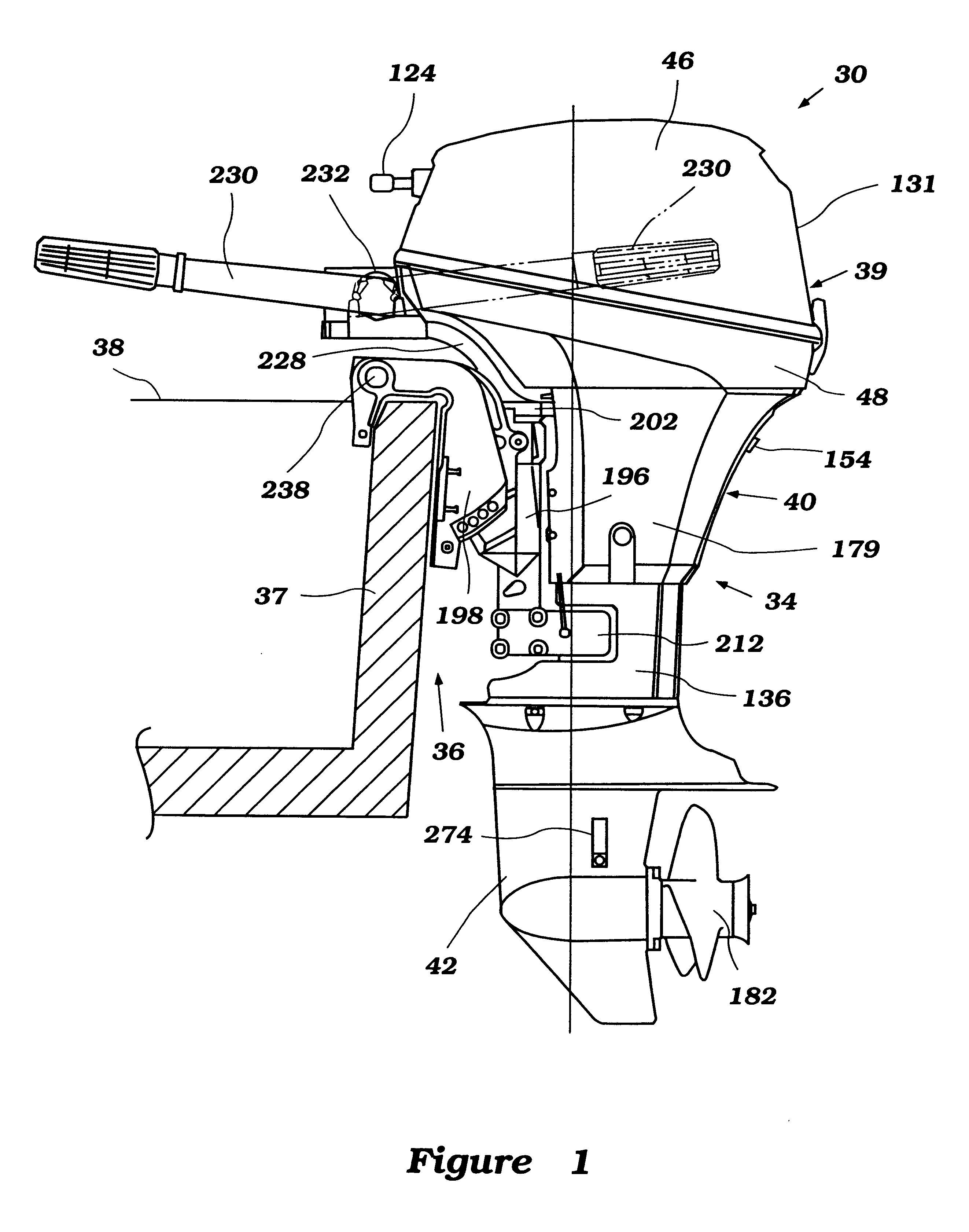
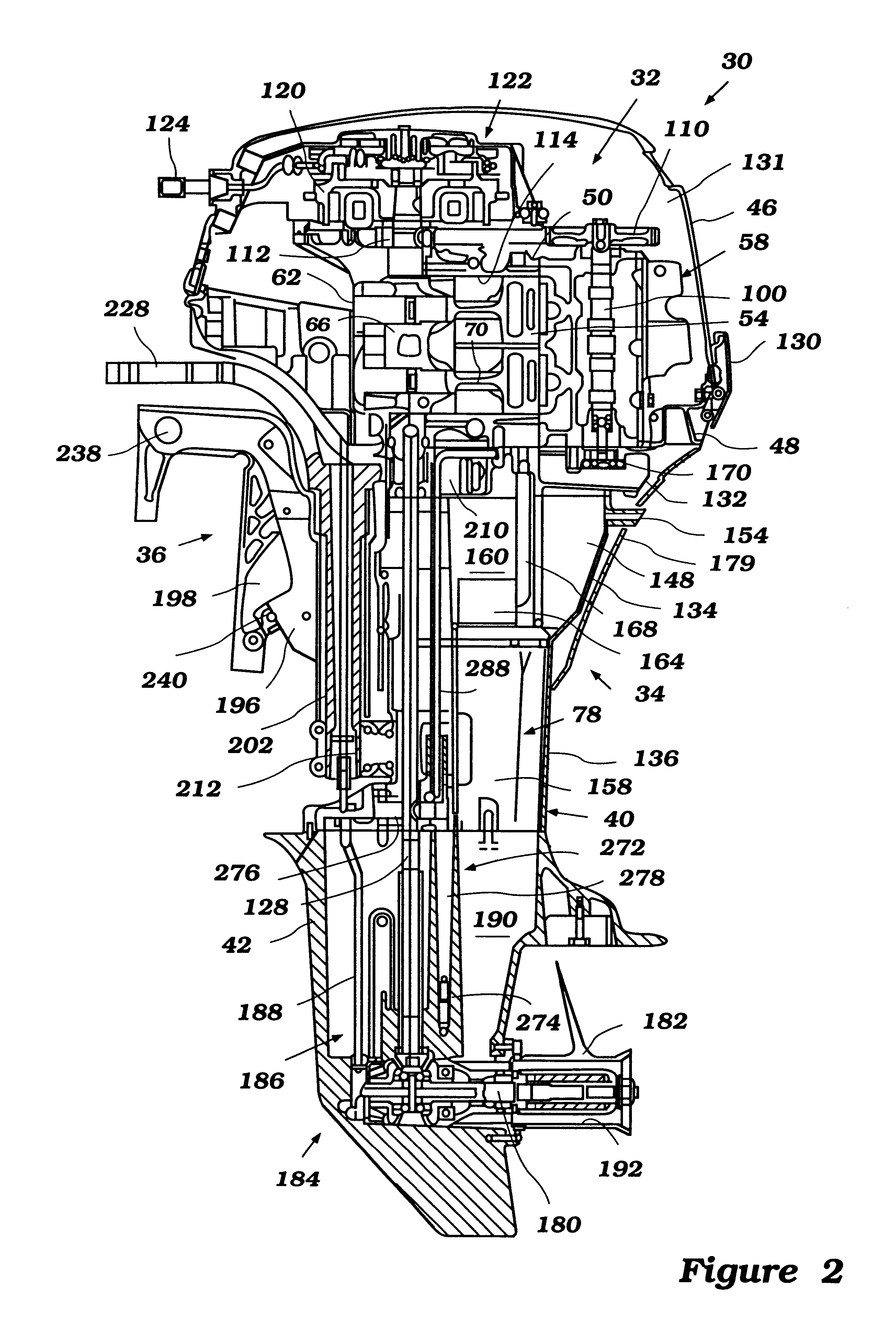
With reference now to FIGS. 1 and 2, an outboard motor, designated generally by reference numeral 30, is illustrated. The outboard motor 30 includes an internal combustion engine 32 arranged in accordance with a preferred embodiment of this invention. In the illustrated embodiment, the outboard motor comprises a drive unit 34 and a bracket assembly 36. The drive unit 34 is affixed to a transom 37 of an associated watercraft 38 by the br...


PUM


Abstract

An improved arrangement of an outboard motor reduces the size of the outboard motor and improves a lubrication system of the outboard motor. Intake and exhaust passages are located along a side of a cylinder body. A crank case lubricant return passage is located on the same side of the cylinder body as the intake and exhaust passages. The return passages have openings located on an inner surface of the crank case. A breather passage connecting a cam chamber and an lubricant reservoir are located on a side of the cylinder body opposite the intake and exhaust passage. The lubricant reservoir including a drain and an insertion port. The insertion port being pointed towards the drain.

Description

1. Field of the InventionThis invention relates to an arrangement of components for an engine, and particularly to an arrangement of a lubrication system, an intake system, an exhaust system and a cooling system for an outboard motor.2. Description of Related ArtThe air intake and exhaust systems of an engine can be arranged in a variety of ways. One of the most common arrangements is a cross-flow type in which the air intake system and the exhaust system are disposed on opposite sides of the engine. Another arrangement, which is not so common, is a counter-flow type in which, unlike the cross-flow type, the air intake system and the exhaust system are disposed on the same side of the engine.There are several advantages to the counter-flow type engine. For example, because the air intake passage is positioned close to the exhaust passage, the intake air charge is warmed by the heat of the exhaust gasses. This expedites engine warm up, particularly during a cold conditions.Another ad...

Claims


Application Information

Patent Timeline
IPC IPC(8): F02B75/20F02B75/00F02B61/00F02B61/04F02B75/18F02B75/02
CPCF02B61/045F02B75/20F02B2075/1808F02B2075/027
Inventor FUKUOKA, YOSHIHITOOISHI, HIROSHIKUMITA, ATSUSHI
Owner SANSHIN KOGYO CO LTD
Why Eureka
Try Eureka