Liquid tank, breather device, and exhaust gas purification device for engine

a technology of exhaust gas purification device and liquid tank, which is applied in the direction of machines/engines, mechanical equipment, transportation and packaging, etc., can solve the problem of liquid storage and flow ou

Inactive Publication Date: 2009-02-12
NISSAN DIESEL MOTOR CO
View PDF6 Cites 24 Cited by
  • Summary
  • Abstract
  • Description
  • Claims
  • Application Information

AI Technical Summary

Benefits of technology

[0008]The present invention addresses the above problems, and provides a structure that makes attachment of liquid to the surroundings of the vent hole unlikely to occur, thereby preventing liquid outflow through the vent hole.
[0013]According to the present invention, inside the liquid tank, the shielding member is disposed so as to surround the vent hole. In the first portion of the shielding member located to the side of the vent hole in the horizontal direction, while air circulation is allowed between the isolated chamber and the inner space of the liquid tank excluding the isolated chamber (“inner space of the liquid tank” and “space inside the liquid tank main body” excludes the isolated chamber unless otherwise stated), while in the second portion, movement of the liquid between the isolated chamber and the inner space is blocked. Consequently, even if sloshing or waving occurs in the liquid inside the liquid tank due to vibrations of the engine or the like when traveling, attachment of the liquid to the surroundings of the vent hole is suppressed by the first portion (excluding the opening) and the second portion, so that liquid outflow via the vent hole can be prevented. The pressure inside the liquid tank is relieved via; the vent hole, the isolated chamber formed by the shielding member, and the opening of the first portion.

Problems solved by technology

However, in a liquid tank having such a vent hole, there is a problem in that vibrations of the engine or vehicle body when traveling cause the stored liquid to flow out to the outside via the vent hole.

Method used


Image

  • Liquid tank, breather device, and exhaust gas purification device for engine
  • Liquid tank, breather device, and exhaust gas purification device for engine
  • Liquid tank, breather device, and exhaust gas purification device for engine

Examples


first embodiment

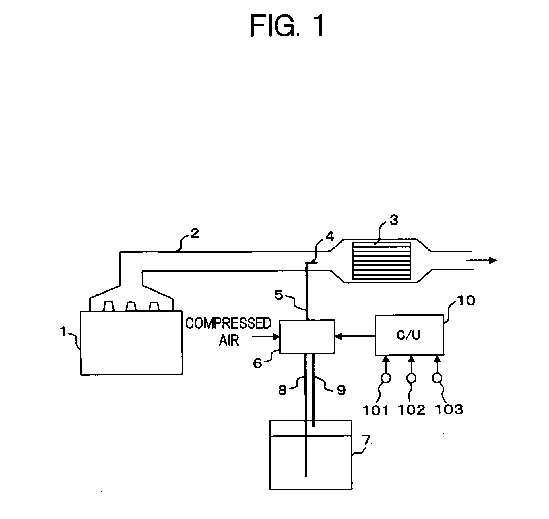
[0027]FIG. 1 is a schematic block diagram of an exhaust gas purification device for an engine, according to the present invention.

[0028]In the present embodiment, an engine 1 is a diesel engine, and is employed to constitute a driving source of a vehicle (here, a large vehicle such as truck).

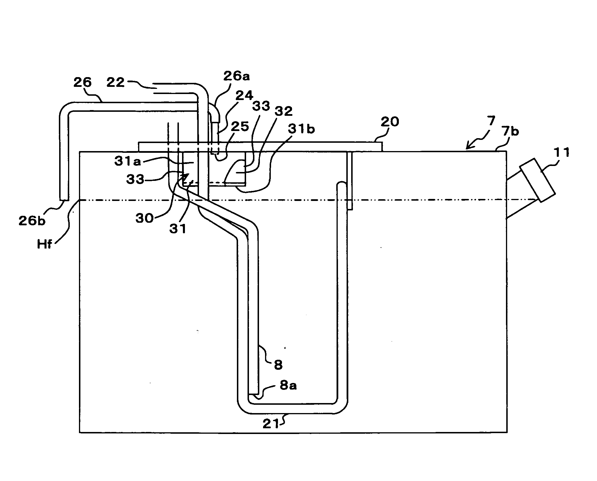
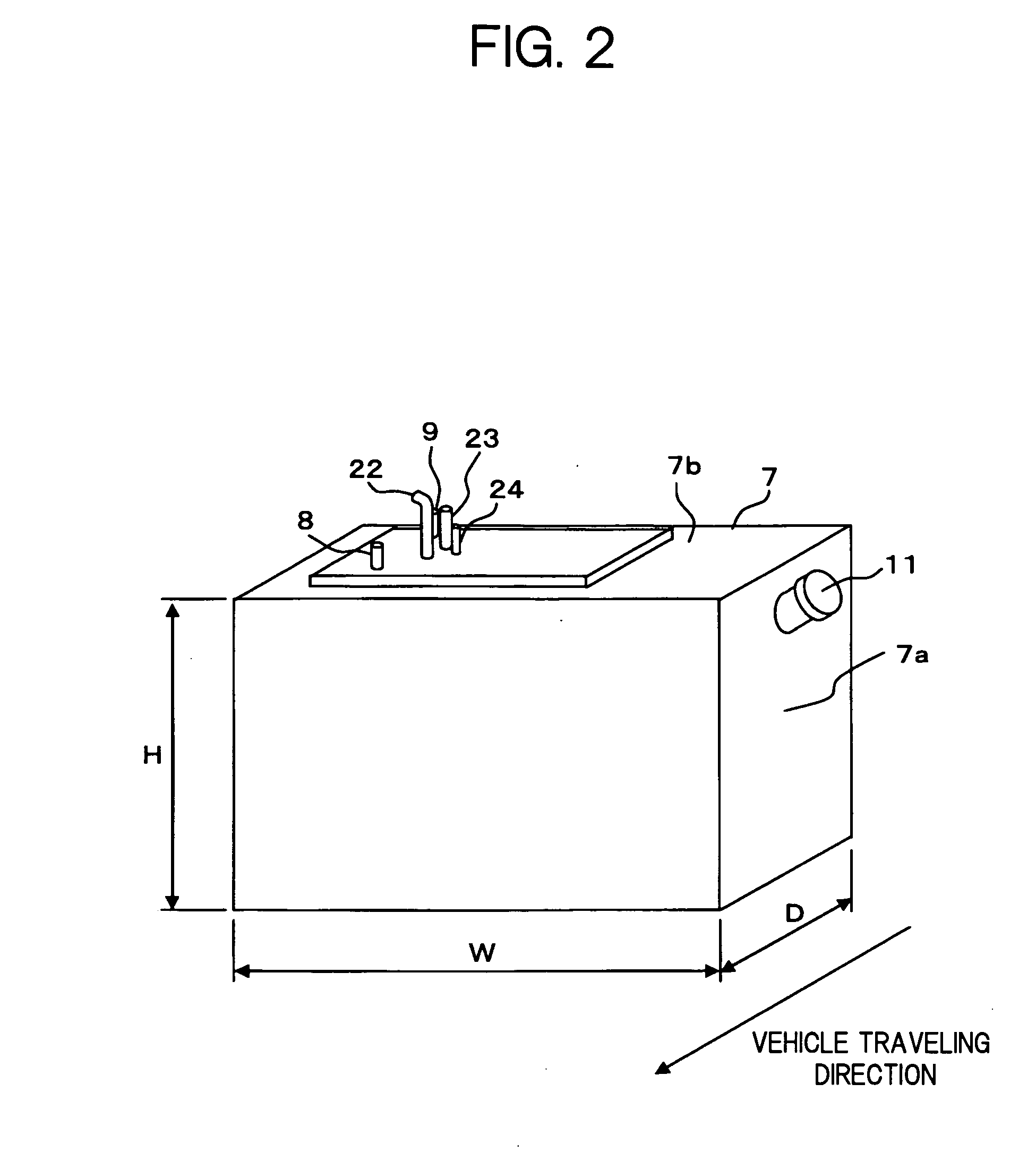
[0029]In an exhaust gas passage 2 of the engine 1, there is interposed a reducing catalytic converter 3 for nitrogen oxides (hereunder, referred to as “NOx”), and this reducing catalytic converter 3 accelerates reductive purification of NOx in engine exhaust gas. In the present embodiment, urea aqueous solution serving as a liquid reducing agent is supplied to the exhaust gas for NOx purification, and a urea aqueous solution injection nozzle 4 (hereunder, simply referred to as “injection nozzle”) is provided on the upstream of the reducing catalytic converter 3. The injection nozzle 4 is inserted into the exhaust gas passage 2 in a manner of passing through the pipe wall of the exhaust gas passa...

second embodiment

[0051]Moreover, in the second embodiment, a portion of the shielding plate also serves a function of the heat transfer plate. However, additional functions of the shielding plate are not limited to this. It is possible to constitute the shielding plate using other components provided in the liquid tank than the heat transfer plate.

[0052]Furthermore, the shape of the liquid tank is not limited to the rectangular shape described above, and it is possible to adopt various shapes. The direction of waves that occur in the liquid tank due to vibrations of the engine during operation is pre-checked, and the shape of the shielding plate (in other words, the position of the opening) is set so that waves occurring in this direction are blocked.

[0053]The present invention is not limited to a liquid tank for storing urea aqueous solution, and may also be applied to a liquid tank for storing other types of liquids, including other liquid reducing agents such as aqueous ammonia and fuel of hydroc...


PUM


Abstract

In a liquid tank provided with a pressure relief vent hole, a shielding member surrounding the vent hole is disposed. The shielding member forms an isolated chamber communicated with the vent hole. In a portion located to the side of the vent hole, the shielding member allows communication between the isolated chamber and an inner space in the liquid tank excluding the isolated chamber. On the other hand, in a portion located below the vent hole, the shielding member blocks movement of the liquid between the isolated chamber and the inner space.

Description

[0001]This application is a continuation of PCT / JP2007 / 052866, filed on Feb. 16, 2007.BACKGROUND OF THE INVENTION[0002]1. Field of the Invention[0003]The present invention relates to a liquid tank, a breather device therefor, and an exhaust gas purification device for an engine. In more detail, the invention relates to a technology for preventing liquid outflow through a vent hole provided for pressure relief, in a liquid tank installed on a vehicle.[0004]2. Description of the Related Art[0005]A vehicle provided with an internal combustion engine (hereunder, simply referred to as “engine”) serving as a driving source, as disclosed in Japanese Laid-open (Kokai) Patent Application Publication No. H07(1995)-208138 (Paragraphs 0024-0027), is equipped with a liquid tank for storing lubricating oil, fuel, and so forth to be used when operating the engine. Moreover, development of an exhaust gas purification device for an engine that uses the urea SCR (Selective Catalytic Reduction) has pr...

Claims


Application Information

Patent Timeline
Patent Type & Authority Applications(United States)
IPC IPC(8): F01N3/10B65D90/34
CPCB60K15/035B60K15/03504F01N3/206F01N3/2066Y02T10/24F01N2610/02F01N2610/10F01N2610/1406F01N2610/1466F01N2610/01Y02A50/20Y02T10/12
Inventor FUKUDA, KIYOSHIOSAKU, YASUSHI
Owner NISSAN DIESEL MOTOR CO
Why Eureka
Try Eureka