Venturi apparatus for pouring and aereating beverages

a technology of aerating apparatus and aerating liquid, which is applied in the direction of liquid transfer device, transportation and packaging, separation process, etc., can solve the problems of device prone to leaking liquid out through air passageways, especially likely to occur, and prior art design problems, so as to facilitate the introduction of air, inhibit vortical flow, and maximize the flow of the first liquid

Active Publication Date: 2012-08-28
FRANMARA INC
View PDF31 Cites 23 Cited by
  • Summary
  • Abstract
  • Description
  • Claims
  • Application Information

AI Technical Summary

Benefits of technology

[0008]The present invention is directed to an improved venturi apparatus for simultaneously pouring and aereating a liquid, such as wine, from a container, that addresses the aforementioned deficiencies in the prior art. In an embodiment of the present invention, the apparatus comprises a conduit through which a first fluid flows, having a constricted intermediate region. One or more lateral tubes for introducing a second fluid at the constricted intermediate region are formed at a substantially acute angle relative to the direction of flow of the first fluid through the constricted intermediate region. The placement of lateral angles of the lateral tubes is selected to maximize flow of the first liquid from the container without overflowing through them.
[0009]In a first preferred embodiment of the invention, the apparatus comprises an entry or inlet section formed to fit into the opening of the container that is fluidly connected to a cylindrical section, which in turn is fluidly connected to an outflow section. A planar segment is disposed upstream of the cylindrical section to inhibit vortical flow. Two diametrically opposed lateral tubes extend from the cylindrical section at substantially acute angles relative to the central and orthogonal axes of the cylindrical section, and are fluidly continuous with the exterior. The lateral tubes facilitate the introduction of air into liquid flowing in the device, and their angled orientation prevents leakage of liquid through the tubes.

Problems solved by technology

However, problems exist in both prior art designs.
Notably, the devices are prone to leaking liquid out through air passageways.
This is especially likely to occur when a large amount of liquid is poured through the devices.
And even so, this may not ensure that leakage does not occur, especially when larger quantities of liquid are poured.
The prior art device is thus unpredictably prone to leakage of liquid, which can cause many additional problems for the user.
A leaked beverage, particularly as with red wine, can result in stains that are difficult to clean.
Such leakage also renders the device itself slippery and difficult to handle, in addition to soiling the user's hand.
Moreover, beverages such as fine wine can be quite expensive, and any loss due to leakage constitutes a cost that must be borne by the user.
The '848 prior art device is also prone to formation of a vortex in the liquid.
Vortical flow causes the liquid to flow along the walls of the cylindrical section and thereby tends to block the movement of air into the liquid.
This blockage thereby reduces the efficiency with which the device can aerate a liquid.
In the '660 prior art device, only one air passageway is provided at an inefficiently designed constriction for producing the venturi effect.
The result is a very slow pouring device and poor aereation.

Method used


Image

  • Venturi apparatus for pouring and aereating beverages
  • Venturi apparatus for pouring and aereating beverages
  • Venturi apparatus for pouring and aereating beverages

Examples


embodiment 100

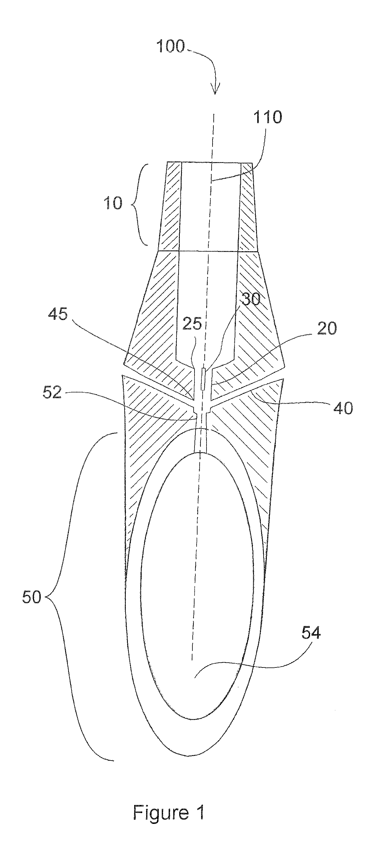
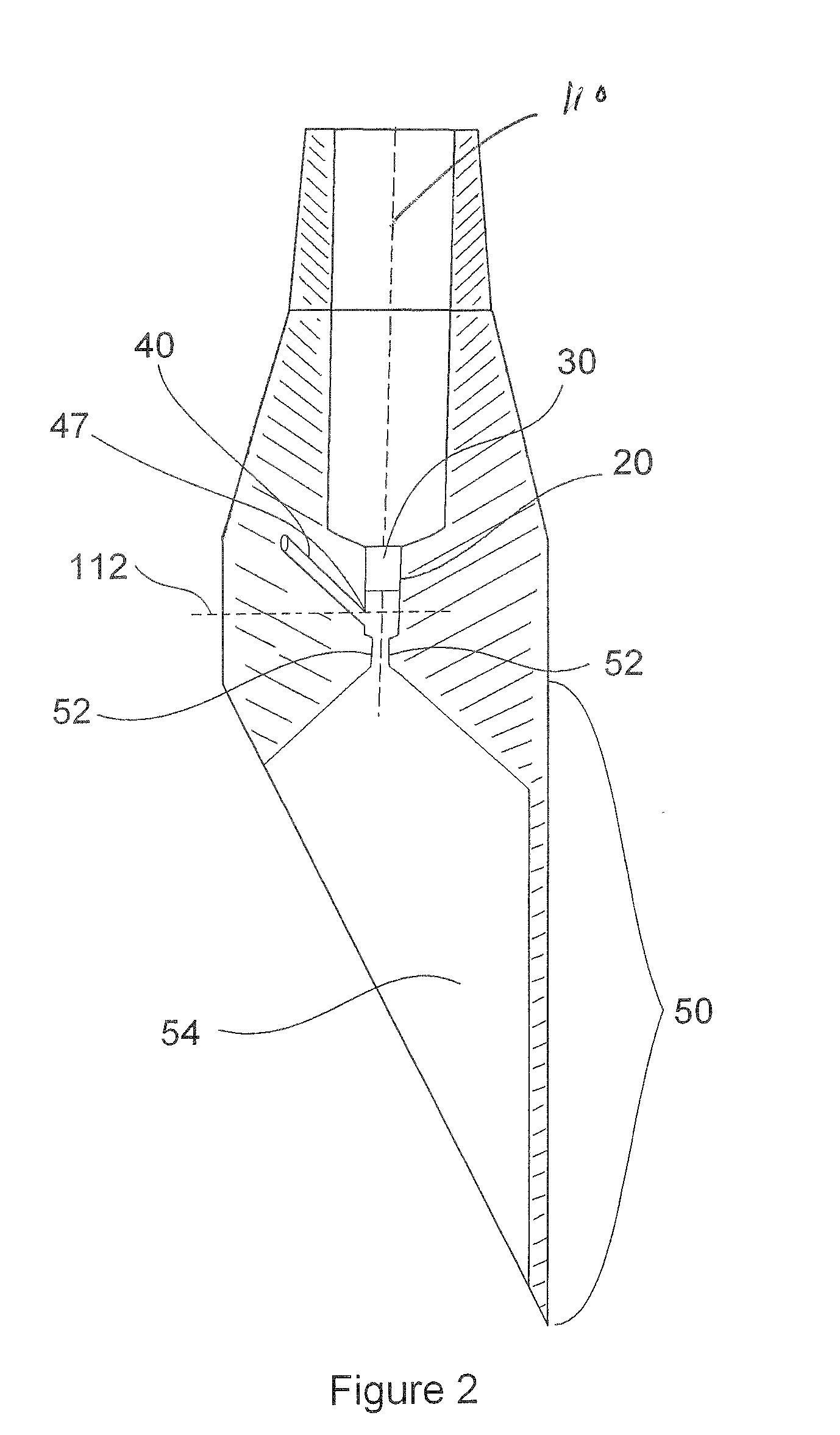
[0021]The present invention is drawn to an improved vertically oriented venturi apparatus for facilitating the aeration of a liquid beverage such as wine. With reference to FIGS. 1-4, an embodiment 100 of the present invention is shown, having central axis 110 and vertical axis 111 and lateral axis 112.

[0022]Entry section 10 has an annular cross-section for conducting the flow of the liquid beverage to the constricted intermediate region, when pouring liquid through the device from a bottle. The inner diameter of entry section 10 is substantially uniform along the axis and direction of liquid flow. The outer diameter of section 10 is tapered to be adapted to fit into the top opening of a bottle, and may comprise or include a soft material for providing a seal between the bottle opening and pourer 100.

[0023]Cylindrical section 20 is fluidly connected at the other end to the narrow end of entry section 10, and centered about central axis 110. Cylindrical section 20 is preferably of su...

second embodiment

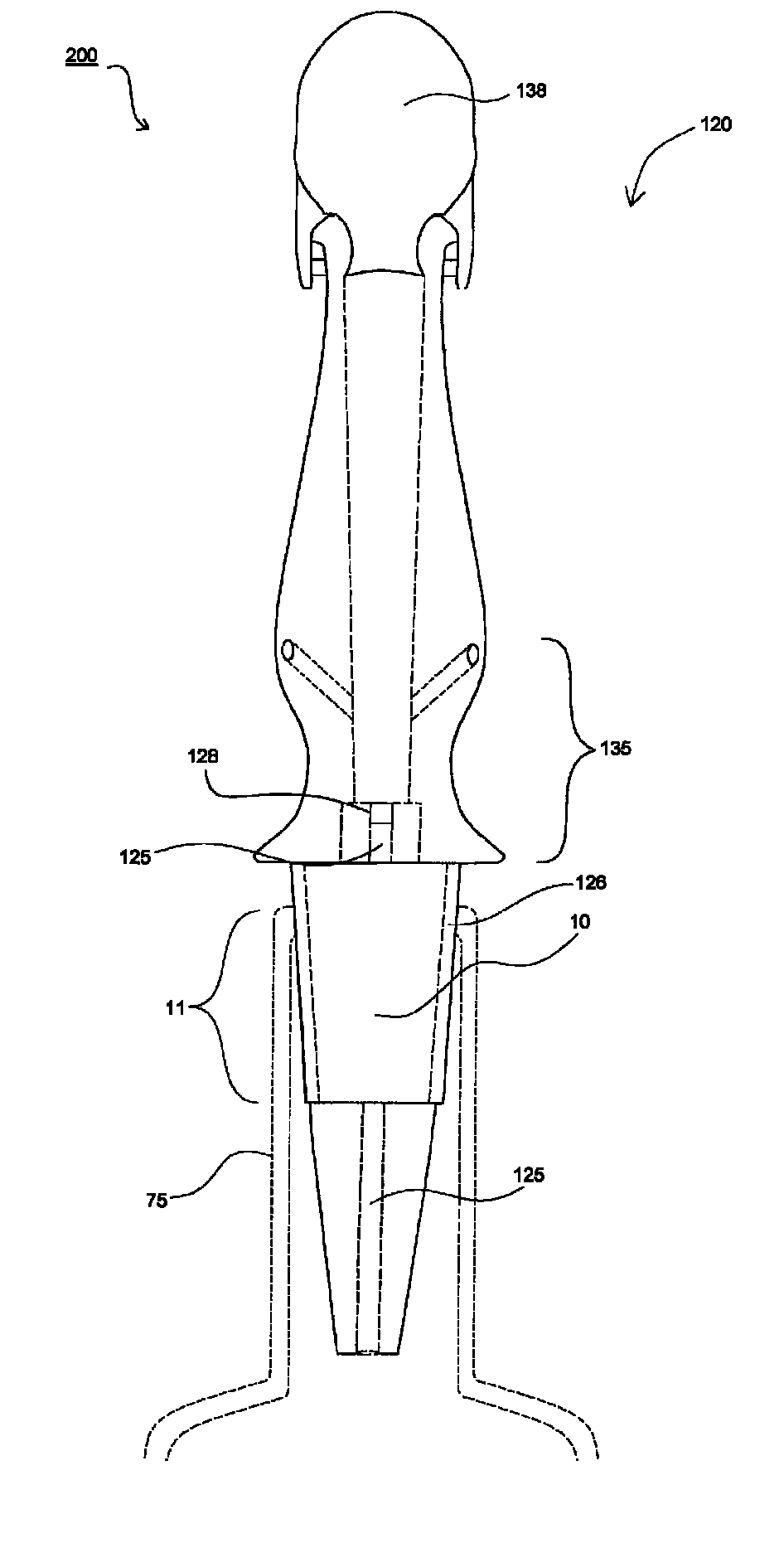
[0029]With reference to FIGS. 5 and 6A, pourer 200 is pourer 100. In particular, section 135 includes all of the elements of pourer 100, and operates in the same or similar way, as described in paragraphs 0021 through 0027 hereof.

[0030]Ventilation or breather tube 125 is disposed along the top of entry section 10. Portion 11 of entry section 10 is extended into the neck of bottle 75 to provide infrastructure for ventilation tube 125, and includes liquid seal coating or sleeve 126 and air intake 128. Sleeve 126 can be made of any deformable elastomer material having a suitable durometer for forming a liquid seal with the inner surface of the bottle opening and which is safe for food service applications. Bottle 75 is presented here for illustrative purposes only and forms no part of the present invention.

[0031]Tube 125 may be formed to fit within entry section 10 as a separate structure, or in conjunction with coating 126. If formed with coating 126, tube 125 can be constructed as a ...


PUM

PropertyMeasurementUnit
angleaaaaaaaaaa
lengthaaaaaaaaaa
lengthaaaaaaaaaa

Abstract

An improved venturi apparatus for the incorporation of air into a liquid. The preferred embodiment of the invention comprises an entry section, a cylindrical section, and an outflow section. Lateral tubes extend from the cylindrical section so as to form an acute angle relative to both the central and cross-sectional axes of the cylindrical section, thereby preventing leakage of liquid out through the lateral tubes during use and subsequent handling. The entry section includes a breather tube connected to the cylindrical section.

Description

CROSS-REFERENCE TO RELATED DOCUMENTS[0001]This application is related to U.S. application Ser. No. 12 / 045,361, filed Mar. 10, 2008, now U.S. Pat. No. 7,992,844.BACKGROUND OF THE INVENTION[0002]The principles of a venturi apparatus are well known in the art. Fluid flowing in a tube that passes through a constricted region experiences both an increase in velocity and simultaneous drop in pressure. The placement of an opening along the area of constriction produces a suction effect due to the decreased pressure of the fluid flowing in that portion of the tube. This principle has been exploited for numerous applications, including flow measurement and the introduction of additional fluids into an existing stream.[0003]As recognized in the prior art, a simple venturi apparatus may be employed to facilitate aeration of a liquid such as wine. One such prior art design consists of a vertically oriented venturi device having a first funnel section connected to a cylindrical section that is i...

Claims


Application Information

Patent Timeline
Patent Type & Authority Patents(United States)
IPC IPC(8): B01F3/04
CPCB01F3/0446B01F5/0428B01F13/002B01F2003/04872B01F2215/0072B01F23/232B01F23/237611B01F25/31242B01F33/5011B01F2101/17B01F23/2326
Inventor CHIORAZZI, FRANKLARIVIERE, F. DAVID
Owner FRANMARA INC
Why Eureka
Try Eureka