Valve assembly

a valve assembly and valve body technology, applied in the direction of valve operating means/release devices, functional valve types, liquid transfer devices, etc., can solve the problems of fuel tank rupture, float valve breakage, difficulty in vehicle movement, etc., and achieve the effect of convenient or commercial choi

Active Publication Date: 2010-09-14
WEIR MINERALS AUSTRALIA LTD
View PDF29 Cites 26 Cited by
  • Summary
  • Abstract
  • Description
  • Claims
  • Application Information

AI Technical Summary

Problems solved by technology

This can cause the fuel tank to rupture from the high pressure attained when filling.
However, when the control valve assembly is mounted to vehicles' fuel tanks, such as those located in trucks and excavators, some difficulties may be experienced during movement of the vehicle.
One problem that may be experience is that the float valve may become broken.
This arm can break due to the large forces that are exerted on the arm by the surging fuel caused by movement of the vehicle.
This may lead to many hundreds or even thousands of liters of fuel being wasted and the spilt fuel being disposed.
Another problem that occurs is fuel is passed through the open breather during movement of the vehicle.
Fuel surges cause fuel to flow through the open breather and escape the fuel tank.
Again, this wastes fuel and is environmentally unfriendly.
Further, the spilt fuel also creates a fire vehicle hazard.

Method used


Image

  • Valve assembly
  • Valve assembly
  • Valve assembly

Examples


Embodiment Construction

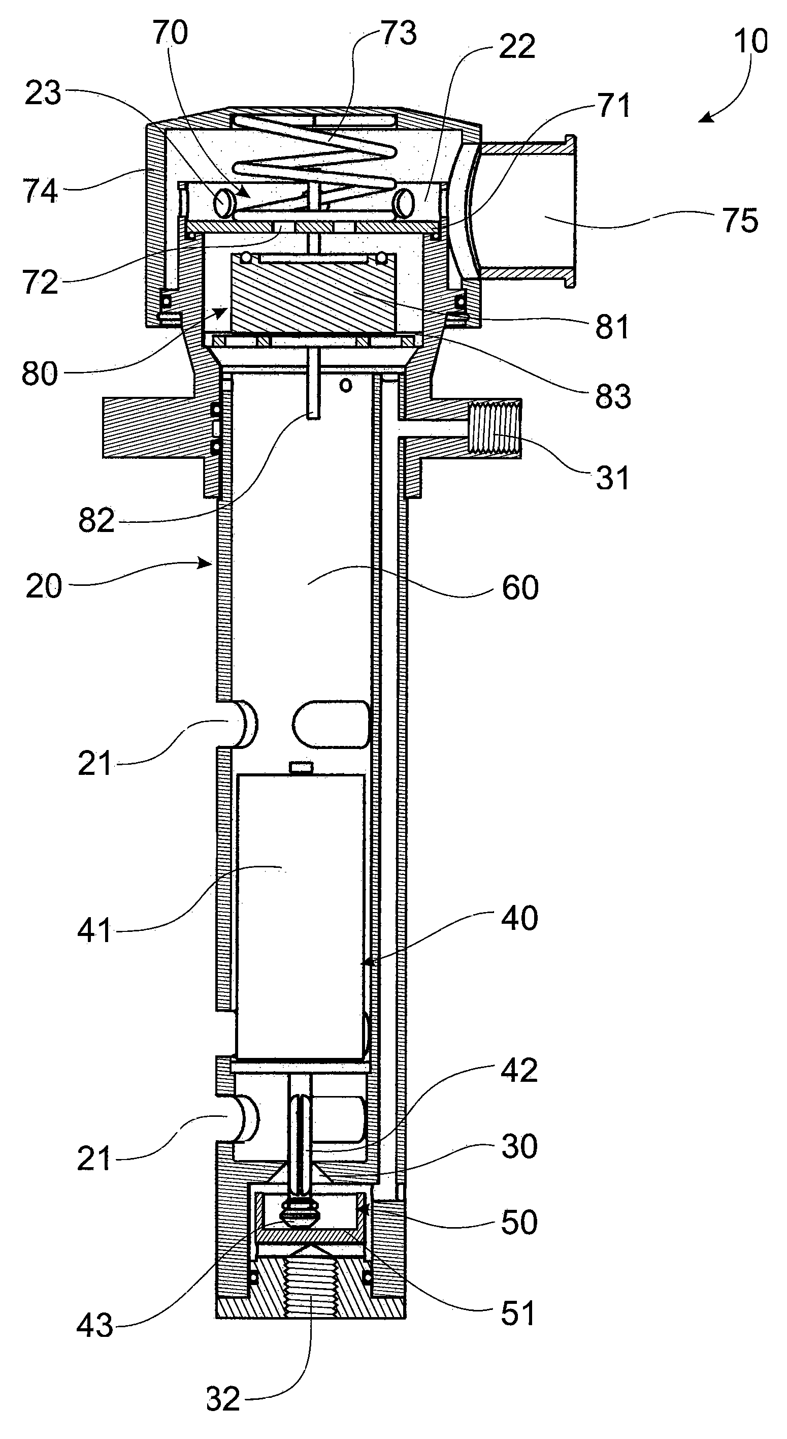
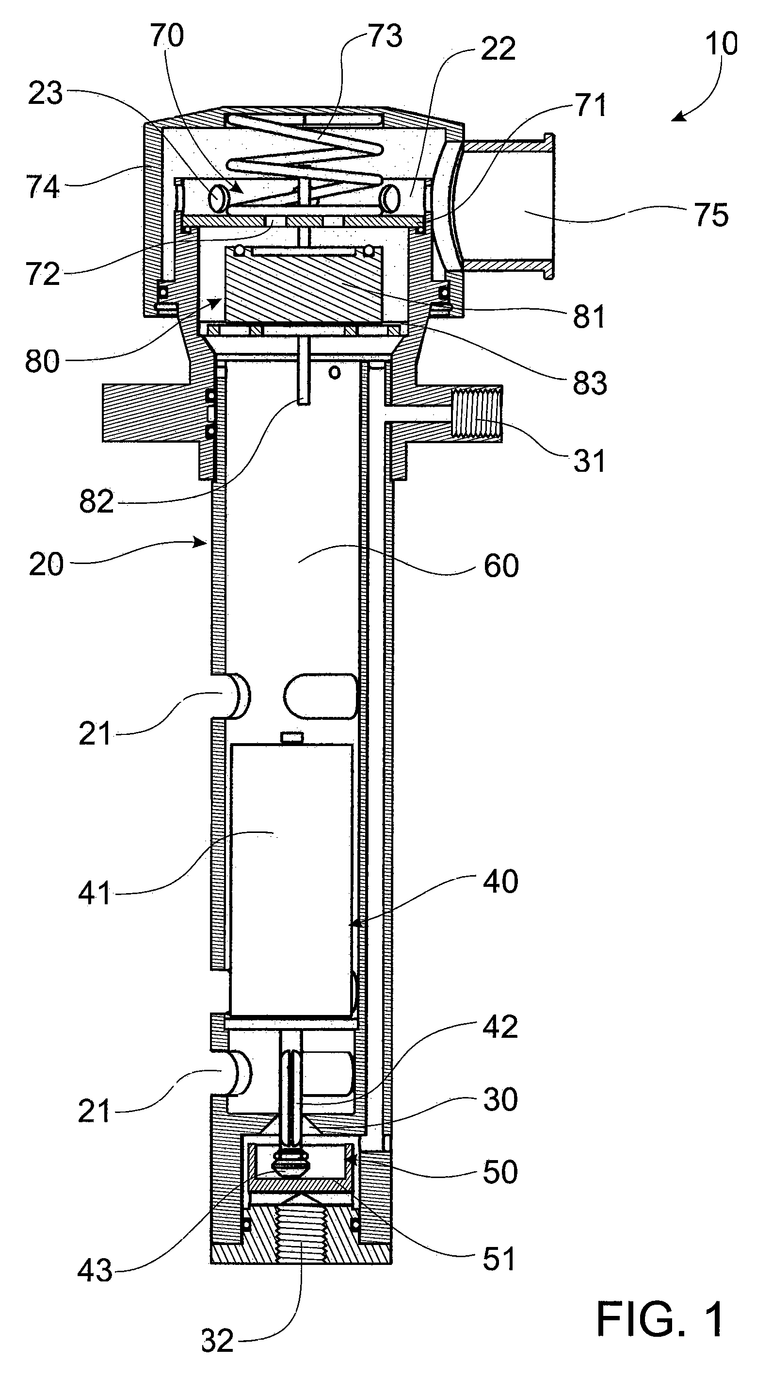
[0027]FIG. 1 shows a valve assembly 10 that is primarily used in a fuel tank 1. The valve assembly 10 is normally used in conjunction with a control valve 2, as described in U.S. Pat. No. 6,311,723, to prevent fuel from entering the fuel tank when the fuel tank has reached a predetermined level. FIG. 6 shows the valve assembly 10 connected to the control valve 2 via a bleed pipe 3. The control valve 2 is connected to a fuel pump 4 and supply tank 5.

[0028]The valve assembly 10 comprises a housing 20 that is hollow and substantially cylindrical in shape. The housing 20 has several fuel holes 21 located along its length that allow fuel located within the fuel tank to pass in and out of the housing 20.

[0029]An inlet 30 is provided at a lower end of the housing 20 through which passes fuel. The inlet 30 is fluidly connected to two separate screw threaded apertures 31 and 32. The bleed pipe 3 is connected to one of the apertures 31 or 32. The bleed pipe is fluidly connected to the control...


PUM


Abstract

A valve assembly (10) able to be mounted with a liquid container, the valve assembly comprising: a housing (20) having a passageway (60) that extends through the housing; a breather float valve (80) mounted within the housing, the breather float valve movable between an open position to allow gas to pass through the passageway and a closed position that prevents liquid from passing through the passageway; a liquid inlet (30), forming part of the housing, the liquid inlet allowing fluid to pass into the housing; and an inlet float valve (41) mounted within the housing, the inlet float valve movable between an open position that permits the flow of liquid through the liquid inlet and a closed position that prevents the flow of fluid through the liquid inlet.

Description

FIELD OF THE INVENTION[0001]This invention relates to a valve assembly. In particular, the invention relates to a valve assembly used to protect fuel tanks from being overfilled with fuel and therefore the invention will be described in this context. However, it is envisaged that the valve assembly may be used to protect the other types of containers from being overfilled with other types of fluid.BACKGROUND OF THE INVENTION[0002]For many years large machinery fitted with fuel tanks have been equipped with fast fill systems to enable rapid filing of large capacity fuel tanks. The existing fast fill fuel systems rely on an air vent that prevents air from escaping the fuel tank when the required level of fuel has been attained. This causes pressure in the fuel tank to increase to a level that automatic shuts-off a fuel supply nozzle.[0003]A major concern of this system is that when the fuel level activates the shut-off for the fuel supply nozzle, the shut-off can be overridden and fue...

Claims


Application Information

Patent Timeline
Patent Type & Authority Patents(United States)
IPC IPC(8): F16K24/04B67D7/36F16K17/02F16K17/26F16K21/18F16K24/00F16K24/02F16K31/18F16K31/20F16K31/22F16K31/34
CPCB67D7/365F16K17/26F16K31/20F16K31/22F16K24/044Y10T137/7465Y10T137/3099Y10T137/0874Y10T137/86332Y10T137/7303Y10T137/7358B67D7/367
Inventor SMIT, PETER MARTIN
Owner WEIR MINERALS AUSTRALIA LTD
Why Eureka
Try Eureka