Electronic breather bag filter

a technology of electronic breather and filter bag, which is applied in the field of filters, can solve the problems of sudden and complete drive failure, deterioration in performance, and reducing the efficiency and longevity of the hard driv

Inactive Publication Date: 2005-08-09
DONALDSON CO INC
View PDF25 Cites 24 Cited by
  • Summary
  • Abstract
  • Description
  • Claims
  • Application Information

AI Technical Summary

Benefits of technology

[0006]The present invention is directed to a filter assembly for use with an electronic enclosure, such as a hard disk drive enclosure containing a rotating disk. In one implementation of the invention, the filter assembly includes a breather bag attached to the outside of the drive enclosure such that there is an air exchange between the filter assembly and the drive enclosure. The filter assembly also typically contains an adsorbent to remove contaminant...

Problems solved by technology

Contaminants, including particles, gases, and liquids within the hard disk drive enclosure can act to reduce the efficiency and longevity of the hard drive.
These contaminants can gradually damage the drive, cause deterioration in performance, and in certain situations can even cause sudden and complete drive failure.
Common sources of contaminants in disk drives include leaks, which may or may not be intentional,...

Method used


Image

  • Electronic breather bag filter
  • Electronic breather bag filter
  • Electronic breather bag filter

Examples


second embodiment

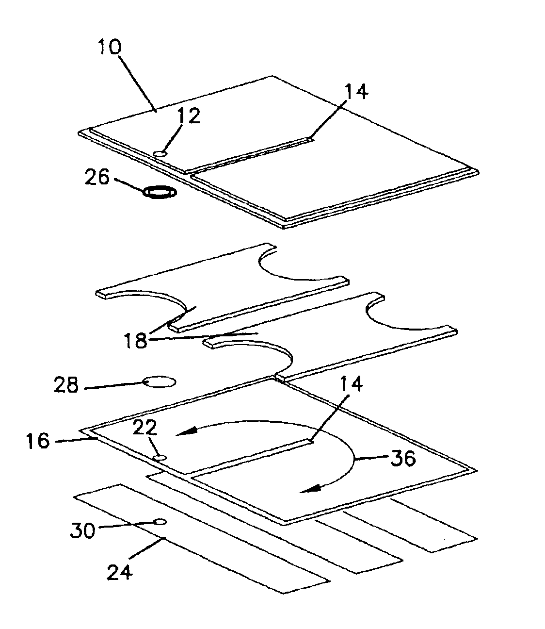
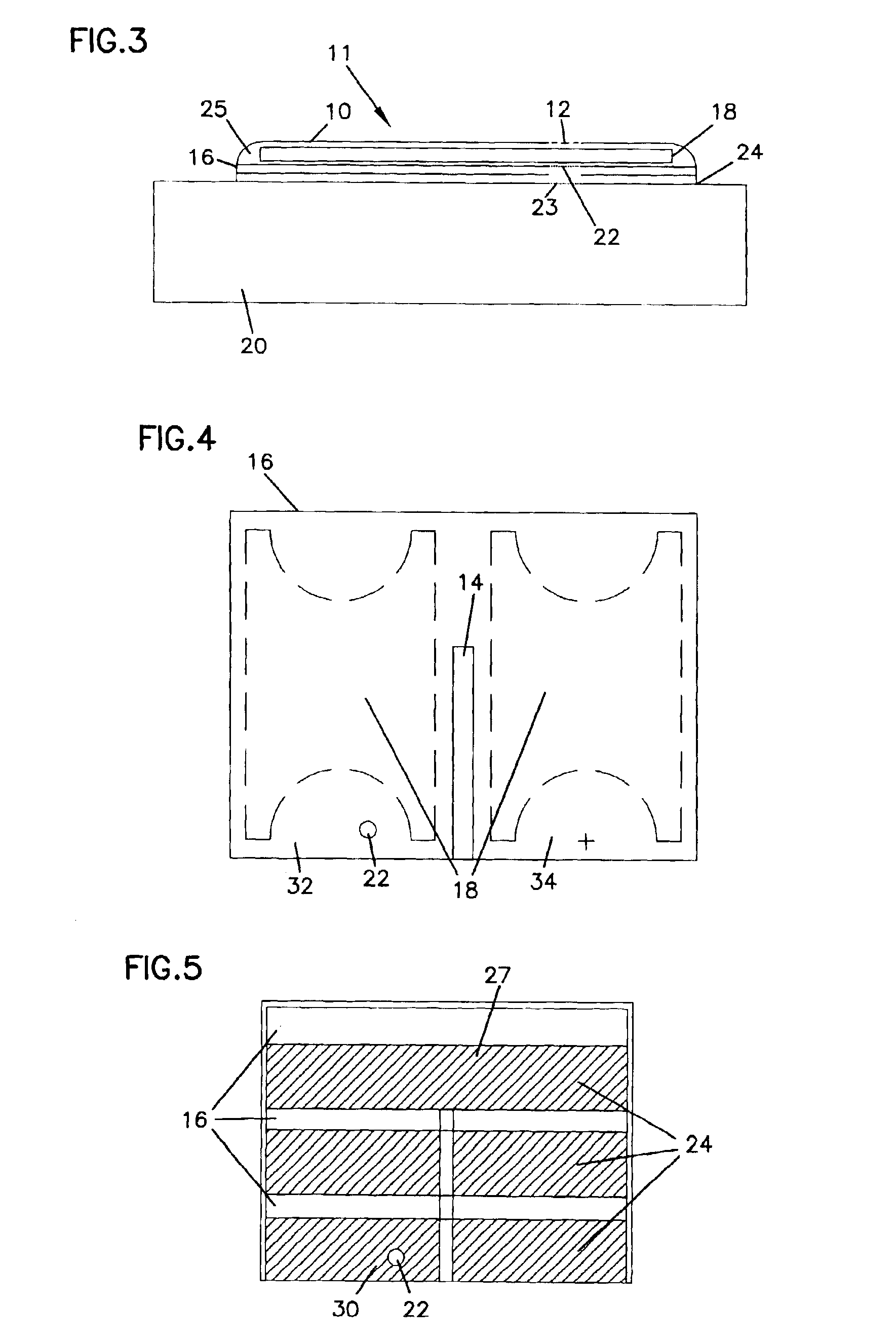
[0032]The filter assembly may take on many different configurations without deviating from the spirit of the invention. Some examples of different configurations are illustrated in FIGS. 6-9, although the invention is not limited to these only. In FIG. 6, a top cut-away view of a filter constructed in accordance with the present invention is shown. Bottom layer 16 is divided by a weld line 14 that connects bottom layer 16 to top layer 10 (not shown). The adsorbent layer 18 resides in the deformable cavity created by bottom layer 16 connected to top layer 10 at the periphery. Attachment hole 22 is disposed near a corner of bottom layer 16. The positioning of weld line 14 close to one side of bottom layer 16 results in a narrow strip of cavity 38 which may function as a diffusion channel depending on its width.

third embodiment

[0033]FIG. 7 shows a top cut-away view of a filter constructed in accordance with the present invention. This embodiment shows one example of a “Z” shaped airflow channel. Bottom layer 16 is connected to top layer 10 (not shown) at the periphery and at two separate weld lines 14. Inside the deformable cavity formed between the top layer and the bottom layer are three adsorbent layer segments 18. Attachment hole 22 is defined by bottom layer 16.

fourth embodiment

[0034]In FIG. 8, a top cut-away view of a filter constructed in accordance with the present invention is shown. This embodiment shows an embodiment where there is no adsorbent layer or airflow channel. Attachment hole 22 is defined by bottom layer 16. The deformable cavity formed by the attachment of bottom layer 16 to top layer 10 (not shown) serves as an air exchange chamber for when air pressure builds up inside the electronic device housing.

[0035]In FIG. 9, a top cut-away view of an additional alternative embodiment of a filter constructed in accordance with the present invention is shown. This embodiment shows a diffusion channel 38 being formed by one of the weld lines 14 being positioned close to the edge of bottom layer 16. The other weld line 14 divides the remaining open portion of the cavity formed between bottom layer 16 and top layer 10 into two larger portions. An adsorbent layer 18 is in each of these two portions.

[0036]Particular elements of the present invention wil...


PUM

PropertyMeasurementUnit
Flow rateaaaaaaaaaa
Lengthaaaaaaaaaa
Electrical resistanceaaaaaaaaaa

Abstract

A breather bag filter assembly for use with an electronic enclosure, such as a hard disk drive enclosure containing a rotating disk, is disclosed. The filter assembly provides filtration of air entering and exiting an electronic enclosure through a breather hole. The filter assembly is a deformable sealed cavity that exchanges air with the drive enclosure as the air pressure inside the drive enclosure fluctuates. In one implementation of the invention the filter assembly contains three layers of material. Two layers of material form the exterior of the filter assembly surrounding a third layer that is composed of an adsorbent material.

Description

FIELD OF THE INVENTION[0001]The present invention relates to filters and to methods for making and using filters. More particularly, the invention is directed to filters for use in preventing contamination from entering electronic enclosures as a result of air exchange into and out of electronic enclosures.BACKGROUND OF THE INVENTION[0002]Hard disk drives and other electronic equipment are often placed within enclosures to provide a clean environment that is necessary for optimal operation of the equipment. For example, hard disk drives normally contain at least one inflexible platter or disk coated with magnetic material that is positioned within an enclosure. The disk is rapidly spun and a magnetic read / write head “flies” a few microns above it in order to access or store data. The magnetic head rides on an air cushion, and it is desirable to position the head as close as possible to the disk without touching it in order to provide a high capacity drive.[0003]Contaminants, includi...

Claims


Application Information

Patent Timeline
IPC IPC(8): B01D46/00B01D46/02B01D53/02G11B33/14
CPCB01D46/0036B01D46/02B01D53/02G11B33/1446B01D2265/04B01D2275/10B01D2279/45
Inventor JOHNSON, CHRISTOPHER M.MCPHAIL, PATRICK L.GARIKIPATI, VIJAY K.LEIER, ANDRE D.
Owner DONALDSON CO INC
Why Eureka
Try Eureka