Method and system for welding railroad rails

a technology for railroad rails and rails, applied in rail joints, manufacturing tools, ways, etc., can solve problems such as difficulty in using the program, uneven narrow gap between rails, and some unsuccessful welding procedures that require a substantial amount of operator attention

Inactive Publication Date: 2001-08-21
LINCOLN GLOBAL INC
View PDF5 Cites 57 Cited by
  • Summary
  • Abstract
  • Description
  • Claims
  • Application Information

AI Technical Summary

Benefits of technology

By using both a low level robotic execution software program and a high level background program, the ideal welding process permanently stored in the data array is modified according to actual welding conditions to accommodate variations in the gap and in the welding process. By using a data array with preselected set steps, or positions, any one step can be modified or replaced without completely rewriting the program. The use of the concept of individual positions associated with specific vertical layers of metal allows changes in specific areas. This is a substantial advance in the arc welding process for welding the joint or gap between spaced railroad rails.
In accordance with the present invention there is provided a method for automatically filling the narrow gap between facing end walls of adjacent first and second railway rails by depositing vertically spaced layers of molten metal in the gap with an electric arc welding torch using a robotic mechanism. This mechanism moves the torch in a path having a pattern determined by a low level robotic executive program. The torch moves from one spatial position to a next spatial position. The method comprises use of a data array for a specific gap. This data array defines an ideal gap and includes a series of positions making up the idealized progression of the torch as it fills the gap in vertically spaced metal layers. Each positions is identified by the location of the torch defined by at least four coordinates, such as x, y and z, together with the rotational coordinates for these axes. The layer is also fixed in the data array. The data array contains the welding parameters to be executed until the next torch position is reached. Consequently, the data array constructed in accordance with the present invention includes a series of positions indicative of the position of the torch and the molten metal layer being processed. The welding pattern performed during the welding step associated with a given position is also stored with the position being processed. The data from the array is outputted for a specific position. The welding parameters for that position, as stored in the data array, are processed using the robotic executive program. Thereafter, the next position of fixed data is outputted and processed by the robotic executive program. This technique of repeating the processing of given selected positions and welding parameters fixed in the data array continues until the total filling process has been completed. By using this method, the data array can be modified individually without rewriting the total program. By using the spreadsheet concept it is possible to utilize a parallel or background program for modifying the individual welding steps. The use of the spreadsheet or data array to provide a fixed series of welding steps is novel in the art of filling the gap between the ends of railroad rails.

Problems solved by technology

The creation of a computer software program for controlling the movement of a robotic mechanism has resulted in somewhat unsuccessful welding procedures that demands a substantial amount of operator attention.
When an executive program is generated by moving a torch in the gap and periodically storing the movement by a software program, difficulty has been experienced when using the program in the field to weld a joint.
The narrow gap between the rails is not uniform from one joint to the next and is not ideal for any joint.
Consequently, robotic control and automatic welding of the gap between spaced rails in the field has not been universally successful from one gap to the next.
The limitation in the past has been the use of a computer software program which is based upon ideal movements of the torch in an ideal, but imaginary, gap.
An unsuccessful filling operation results in a rejected joint.
This is unacceptable and somewhat mitigates against successful implementation of a computer controlled robotic mechanism for filling the joint between spaced rails.
The spacing of the end wall is not always the same; consequently, use of an ideal torch movement is not always successful in providing a satisfactory weld joint.

Method used


Image

  • Method and system for welding railroad rails
  • Method and system for welding railroad rails
  • Method and system for welding railroad rails

Examples


Embodiment Construction

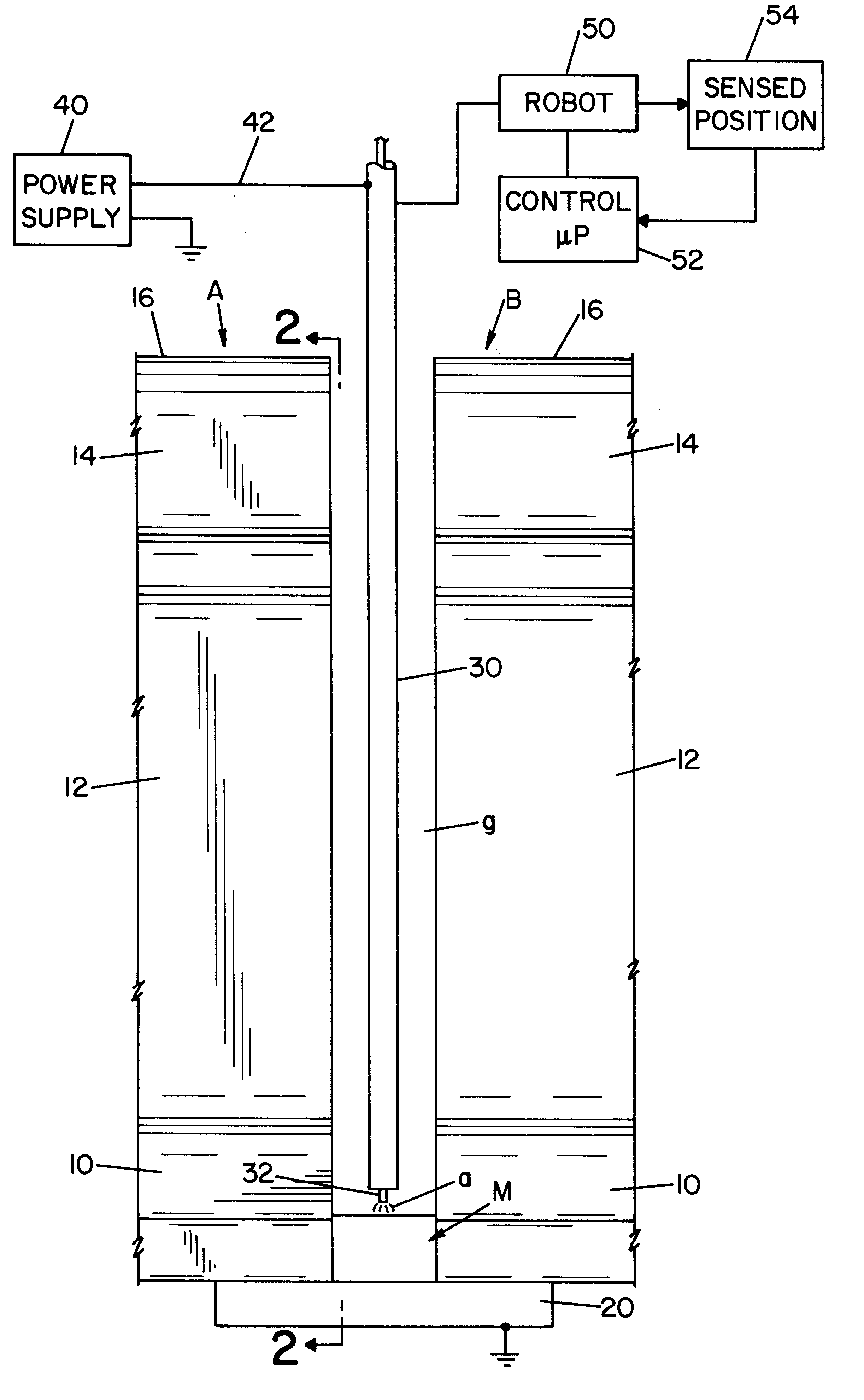
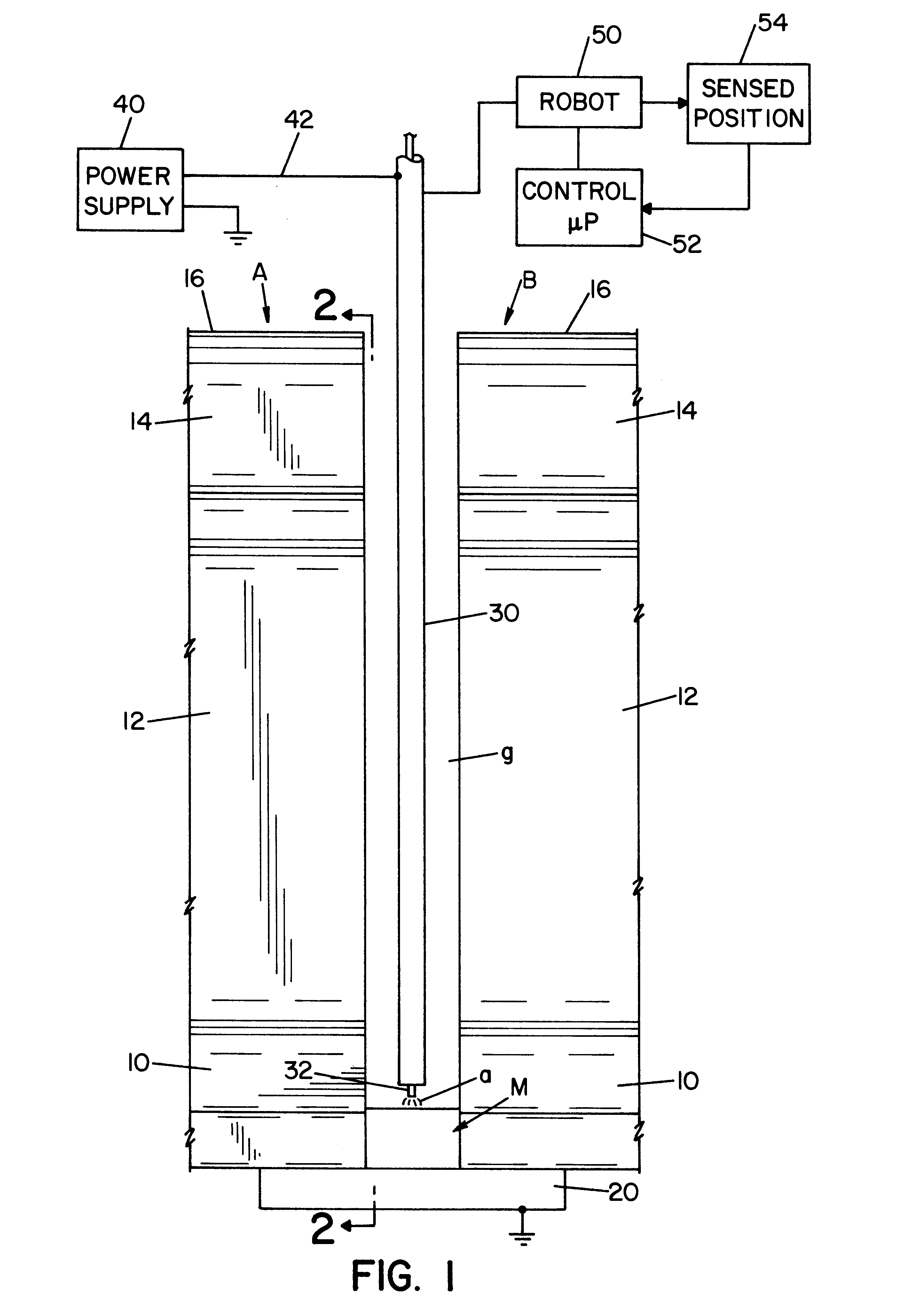
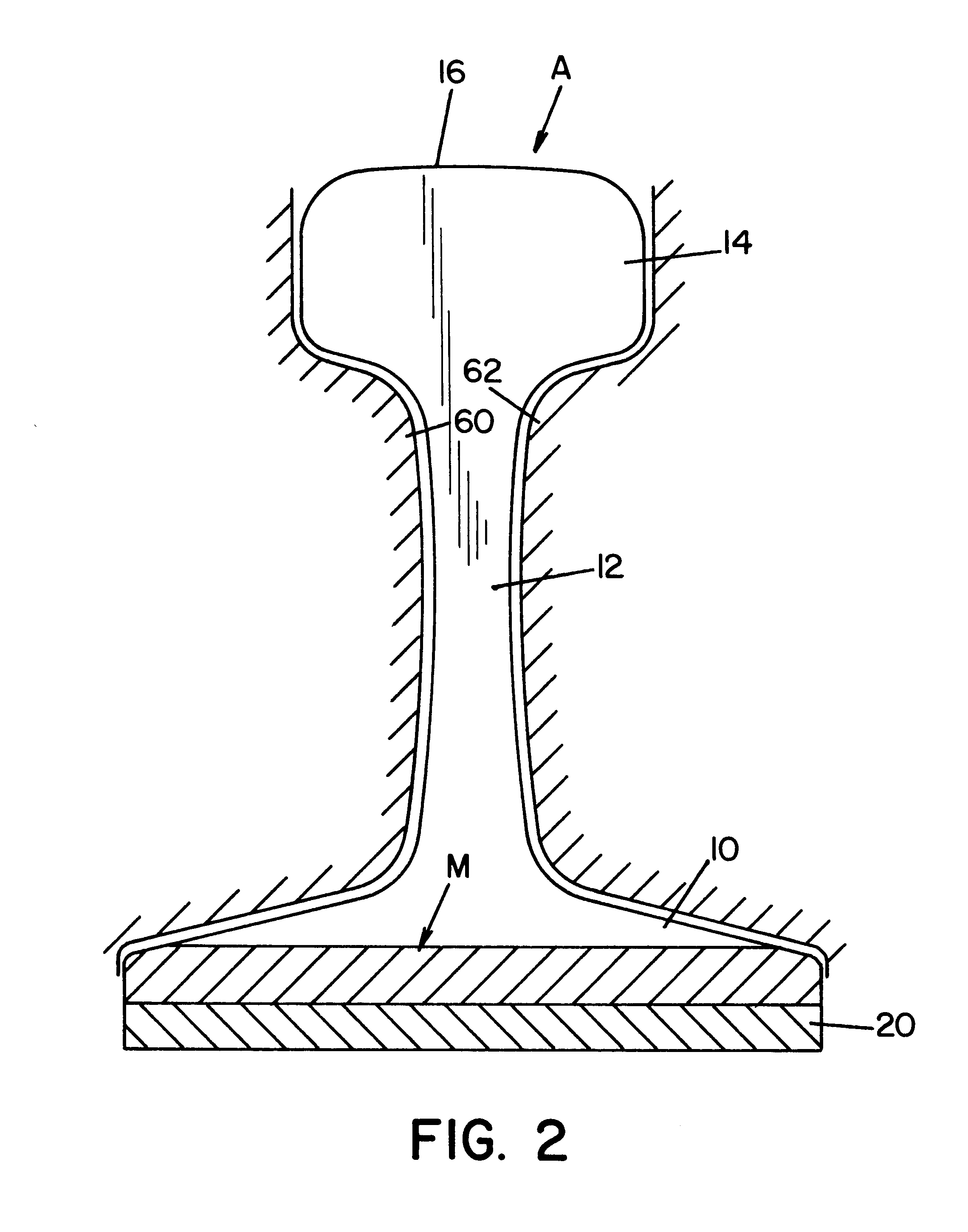
Referring now to the drawings wherein the showings are for the purpose of illustrating a preferred embodiment of the invention only, and not for the purpose of limiting same, FIGS. 1 and 2 show railroad rails A, B, each having a standard base 10, web 12, head 14, and upper cap 16. To create electrical continuity for the arc welding process, spaced rails A, B, are grounded together by backplate 20, which closes the lower portion of vertically extending gap g. This gap is filled by an electric arc welding process as described in Morlock U.S. Pat. No. 5,773,779 and Morlock U.S. Pat. No. 5,877,468 whereby molten metal M is deposited in gap g by a torch 30 through which is advanced a welding wire or electrode 32. A standard power supply 40 has a lead 42 electrically connected to torch 30 for creating the voltage between electrode 32 and the molten metal puddle or bead M. In accordance with standard welding technology, the voltage between electrode 32 and metal M causes an electric arc a,...


PUM

PropertyMeasurementUnit
Heightaaaaaaaaaa

Abstract

A method and system for automatically filing the narrow gap between facing end walls of adjacent first and second railway rails by depositing vertically spaced layers of molten metal in the gap with an electric arc welding torch using a robotic mechanism that moves the torch in a pattern controlled by a low level robotic execute program from a spatial position to a next spatial position, said method and system comprising: constructing a data array for a specific gap, said array constituting a series of positions making up an idealized progression of said torch to fill said gaps in vertically spaced layers made up of multiple positions, each of said fixed positions identified by at least four coordinates, including (1) at least x, y and z, (2) the layer in which said position is a part and (3) the welding parameters to be executed while said torch moves toward the next position; outputting data relating to a specific position from said data array; processing said welding parameters associated with said outputted data using said robotic execute program; then, outputting the new fixed data relating to the next position in said series of points; processing said welding parameters associated with said new data using said robotic execute program; and, repeating said outputting and processing acts until said positions in said data array relating to a specific layer have been processed. Thereafter the method or system repeats the layer or processes the next layer comprising multiple stored positions.

Description

The present invention relates to a method and system for welding the spaced ends of rails and more particularly to welding two spaced railroad rails by using an electric arc welding process.BACKGROUND OF INVENTIONThe narrow gap between facing end walls adjacent first and second railway rails must be filled accurately and rapidly with molten metal if an electric arc welding process is to be successfully used in the field. To accomplish this objective, technology has advanced to the concept of moving the electric arc welding torch back and forth in the gap by a robotic mechanism. In the past, the movement of an electric arc welding torch is controlled by a robotic mechanism by use of an executive software program using somewhat low level language. The program is created by moving the torch in the desired path and recording this movement in program language so that the movement can be duplicated when the next rail joint is being filled. The creation of a computer software program for c...

Claims


Application Information

Patent Timeline
IPC IPC(8): B23K9/02E01B29/42E01B11/50E01B11/00E01B29/00B23K9/00B23K9/095B23K9/16B23K101/26
CPCB23K9/0213E01B29/42E01B11/50B23K2201/26B23K2101/26
Inventor MORLOCK, MICHAEL J.MUMAW, JAMES W.
Owner LINCOLN GLOBAL INC
Why Eureka
Try Eureka