Variable baud rate demodulator

a demodulator and variable baud rate technology, applied in the field of demodulation of digital signals, can solve the problems of cumbersome and expensive implementation of additional and/or different filtering for each received baud rate, limited baud rate adjustment to a few hundred or thousands of parts per million, and inability to adjust through a wide range of baud rates

Inactive Publication Date: 2001-08-28
LUCENT TECH INC +1
View PDF4 Cites 56 Cited by
  • Summary
  • Abstract
  • Description
  • Claims
  • Application Information

AI Technical Summary

Problems solved by technology

However, these conventional baud rate adjustments are limited to just a few hundreds or thousands of parts per million of the baud rate, and are not able to adjust through a wide range of baud rates without requiring additional and / or different filtering for each different baud rate.
The need for additional and / or different filtering for each received baud rate is cumbersome and expensive to implement.

Method used


Image

  • Variable baud rate demodulator
  • Variable baud rate demodulator
  • Variable baud rate demodulator

Examples


Embodiment Construction

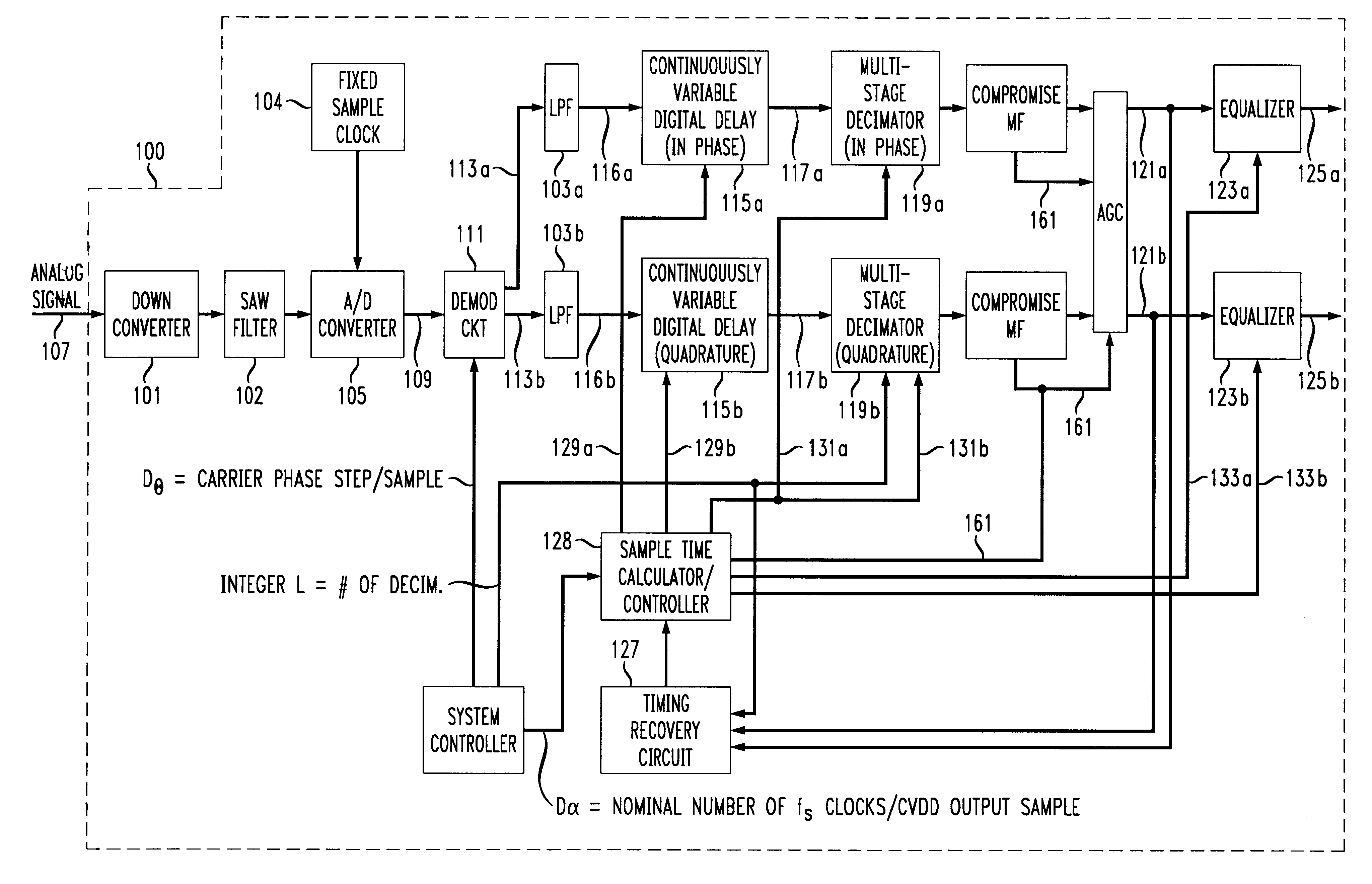
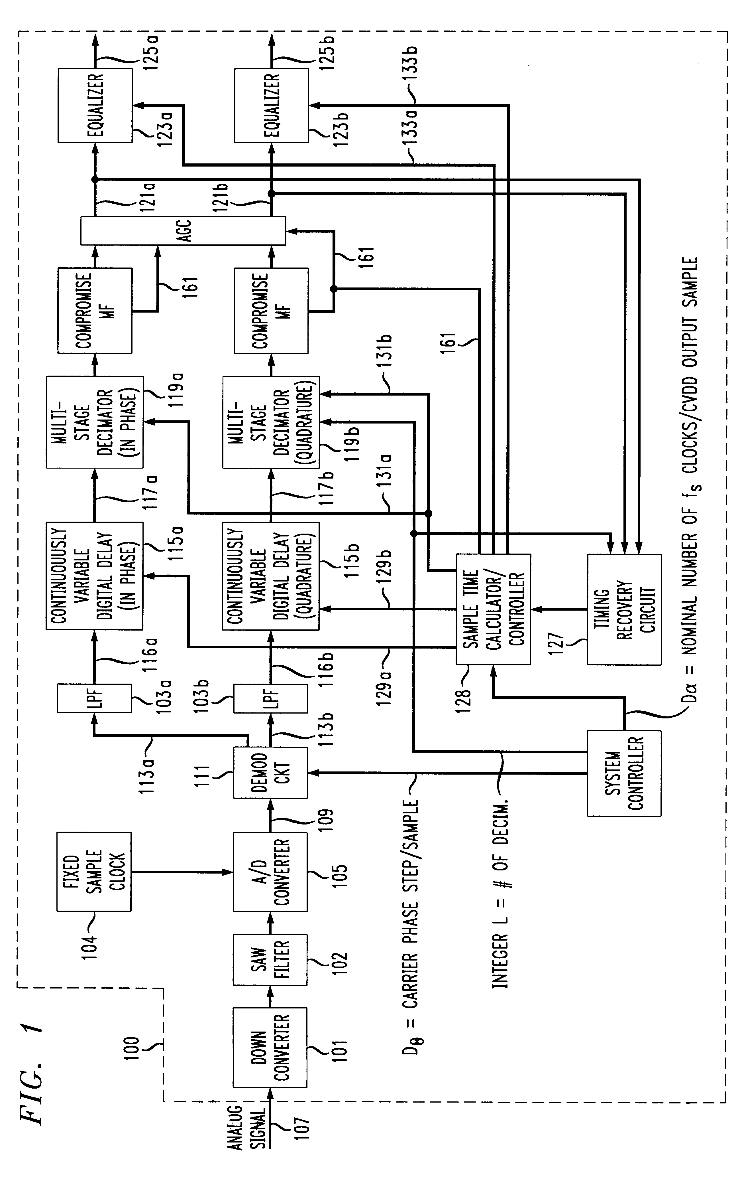
The present invention provides a demodulator which has the bility to efficiently receive and demodulate a modulated transmit signal having any of a wide range of baud rates. Importantly, rather than adjust the sampling rate of the digital signal as the baud rate changes as in conventional devices, the present invention utilizes a fixed sampling rate no matter what the desired or target baud rate is, and adjusts the desired baud rate with a continuously variable interpolator / decimator device.

FIG. 1 shows a first embodiment of a demodulator 100 in accordance with the principles of the present invention. While the present invention is shown with respect to a modem receiver, the principles of the present invention are applicable to other demodulators and receivers such as in high definition television (HDTV) receivers and / or receivers making use of the vestigial side band (VSB).

FIG. 1 shows a downconverter 101, SAW filter 102, AND converter 105, demodulator circuit 111, low pass filters...


PUM


Abstract

A method of efficiently demodulating and isolating a signal within a fixed possibly wider band spectral region, having any of a wide range of baud rates. The signal is sampled at a fixed, first frequency which remains fixed no matter what the baud rate. Thus, the sample rate does not necessarily correspond to the desired baud rate. The sampled signal is then demodulated and low pass filtered to create baseband samples at the first frequency, which are then subject to user-specified arbitrary rate change in a continuously variable interpolator/decimator (continuously variable digital delay (CVDD) device), and decimated by a programmable power of 2, to produce samples at a second frequency. The second frequency is preferably determined to be a whole number multiple of the desired baud rate, e.g., twice the desired baud rate. The samples are equalized to produce output symbols at the target baud rate. Based on this method, a demodulator can receive signals of varying bandwidth and baud rates at arbitrary spectral locations within a possibly wider bandwidth aggregate channel span, and can adapt its target baud rate for each signal to be the actual baud rate of the derived incoming data signal within the possibly wider bandwidth aggregate channel span.

Description

1. Field of the InventionThis invention relates generally to the demodulation of a digital signal. More particularly, it relates to an adaptive technique for demodulating a modulated digital signal having a widely variable baud rate.2. Background of Related ArtHigh speed data transmission systems, e.g. modems, operate in general by modulating a high frequency carrier corresponding to a desired channel with a low frequency digital signal at a fixed baud rate. The modulated data signal is transmitted to a receiver, which demodulates the received high frequency modulated signal to recover digital symbols at the desired baud rate.In such data transmission systems, the baud rate of the transmitting and receiving devices are generally fixed at a discrete level, and generally include a modulator and / or demodulator which operates at a fixed baud rate. Any fine adjustments which might be made in the baud rate of the receiver are typically made in the sampling rate of an analog-to-digital (A / ...

Claims


Application Information

Patent Timeline
Patent Type & Authority Patents(United States)
IPC IPC(8): H04L27/38H04L7/02
CPCH04L27/38H04L7/0029
Inventor FARROW, CECIL WILLIAMUDOVIC, DANIELRAGHUNATH, KALAVAI JANARDHAN
Owner LUCENT TECH INC
Why Eureka
Try Eureka